
Feedback Delay
About This Guide
This Application Note explains the use of the Feedback Delay module in the Audio Weaver Application. The Feedback Delay module can be found in Sound Design/Control folder or by using the search window in the module browser. It is called “General Interpolated Delay with Feedback Gain”.
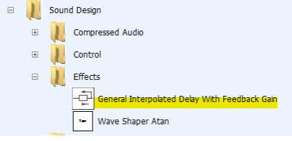
Figure 1. Location in Module Browser
The Feedback Delay Module
This module implements a time-varying delay, with feedback gain control. The first input pin (mod) specifies the modulation factor; the second input pin is the multichannel audio signal. The module computes the instantaneous delay to apply on a sample-by-sample basis. The instantaneous delay is a floating-point value computed as:
delay[n] = M.currentDelay + mod[n] * M.modDepth
The modulation factor input is usually in the range [-1 +1], but this is not checked by the module.
The output of the module is given by:
output[n] = input[n] + fGain * delay[n]
The instantaneous delay time is a floating-point value, and the module implements fractional sample interpolation using linear or cubic (third order) interpolation.
The Feedback Delay module allows construction of Delay functions where the amount of feedback and the level of the delay signal are set by the same parameter. An example is given using this module to create a “resonator” which is used to make “notes” appear from the input signal by enhancing harmonics that correspond with the delay time.
Internal structure and properties
This diagram shows the structure of the Feedback Delay module.
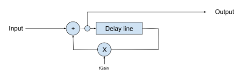
Figure 2. Feedback delay internal structure
Delay is calculated as:
delayIndex = (mod[i] * modDepth) + currentDelay;
Perform interpolation to read the sample and apply feedback gain:
out[i] = in[i] + fGain * delaySample;
Note that the input signal is always mixed into the output and that fGain adjusts both the feedback amount and the amount of delay in the output. With the fGain parameter turned all the way down, there is no feedback and there is no delay in the output signal. Therefore, you cannot have “high feedback and low delay mix level” or “low feedback and high delay mix level”.
Module arguments
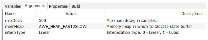
Figure 3. Module arguments
maxDelay should be set to the maximum of (currentDelay + modDepth). See below for descriptions of these parameters. All parameters are in samples.
memHeap – where to locate the RAM used by the delay module. The available options will depend on the configuration of your BSP.
interpType
Interpolation allows “between-sample” delay times to allow fine tuning
Linear - lower quality, low CPU use
Artifacts affect high frequencies
Cubic - higher quality, higher CPU use
Module variables
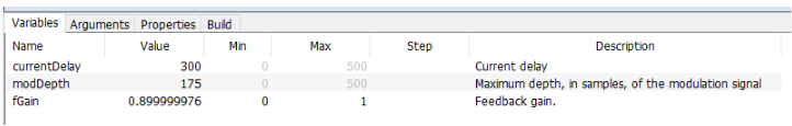
Figure 4. Module variables
currentDelay – the center point of the delay setting. If modDepth = 0, or the value of the mod signal is currently 0, then the actual delay will be currentDelay.
modDepth – how far (in samples) to change the delay in response to a modulation signal at its maximum expected amplitude of 1.0.
fGain – the amount of feedback gain (linear)
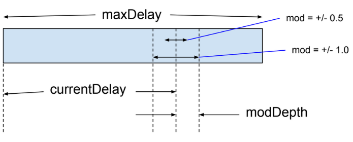
Figure 5. Relationship of settings
Example dual resonator design
The Resonator-Test.awd file shows the use of the Feedback Delay module as a resonator. There are two delay lines panned hard left and hard right listening to the stereo input signal. The delay time settings and modulation levels are individually settable. A percussive drum beat WAV file is included for testing to highlight the action of the resonator.
The feedback gain is set simultaneously on both modules using a pair of ParamSet modules driven by a DC Source. Note that the feedback gain must be around 0.95 or higher before you notice the resonance effect.
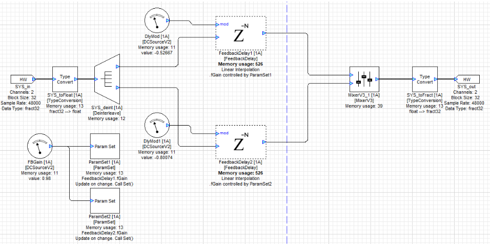
Figure 6. Example dual resonator design
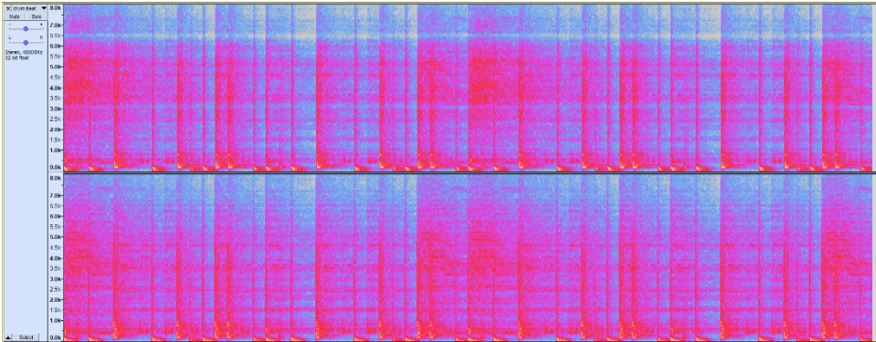
Figure 7. Spectrogram of drum beat WAV file before processing
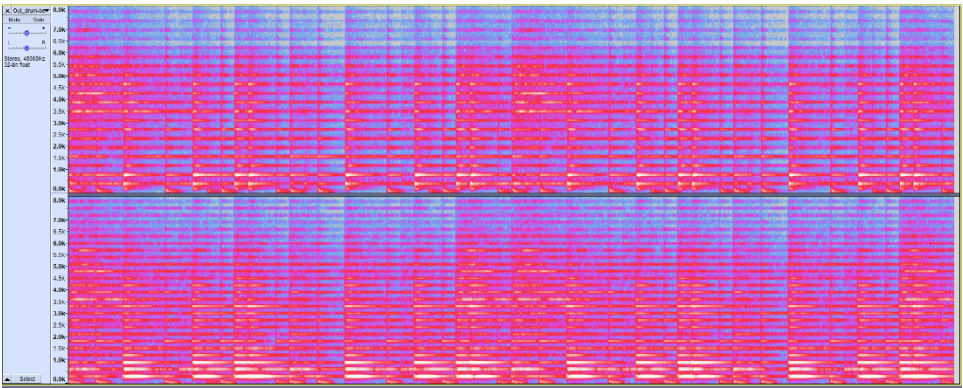
Figure 8. Spectrogram of drum beat WAV file after processing
As you can see and hear, the processed signal has enhanced the signal energy at frequencies whose periods correspond to integer divisions of the delay time. This is shown in Figure 8 by the strengthened horizontal lines indicating the amount of energy. The frequencies are evenly spaced on a linear scale. The spacing for the left and right channels is different as the delay times were different when the recording was made.
By adjusting the delay time, a distinct set of harmonics can be enhanced, which can enhance notes where they already exist, or seemingly create notes from noise. The subjective effect of changing the delay time while processing a signal with broadband energy (such as a drum track or noise) is a tone that gets lower when the delay time is increased, and higher when the delay time is decreased.
The interpolated delay line allows smooth transitions from one delay time to the next, although the Mod input is not smoothed. It also allows you to set more precise resonance frequencies compared to a non-interpolated delay line.
By carefully tuning a set of 3 or more Feedback Delay modules to resonate at desired frequencies, resonant chords can be created.