
Signal Flow Best Practices
Overview
Automotive audio signal flows are complicated and need to be properly designed to be deployable and easy to maintain. Several core design decisions need to be made which take into account the Snapdragon software architecture and Audio Weaver best practices. These need to be considered at the start of the project to minimize rework later on. The main areas to consider are:
Which processors boot early and which boot late
Early audio feature requirements
10 MB limitation on boot files for early audio. This includes
Signal flow data
WAV playback data
The flash file system
How to implement late chimes that require more WAV data
Progressive loading of the signal flow
Low latency support for RNC
TDM port usage
Which TDM port will be the Synchronous master?
How to minimize I/O latency for RNC processing
Control architecture
Leveraging control arrays to centralize control
Chimes control during early audio
Full control during late audio
How Subcanvases can be leveraged for encapsulating and loading features
Late loading custom modules via DLLs
Factory flashing and customization of vehicle audio
Supporting OTAs and downloadable audio features
The design principles are embodied in the “SnapdragonGen5_Reference.awd” signal flow. We will use this system throughout to highlight how to implement features in Audio Weaver.
This document focuses on the Qualcomm Gen 5 Snapdragon (SA8797, SA8793, etc.) but most of the principles apply to the Gen 4 SOCs. The main difference to consider is the differences between early and late boot processors:
Function | Gen 4 | Gen 5 |
Early boot processors | ADSP, GPDSP0, GPDSP1 | DSP0 |
Late boot processors | Arm | DSP1, DSP2, Arm |
Signal Flow Planning
The signal flow designer must distribute features across the different processing cores. There are several items which must be considered upfront:
What features are needed for early audio?
What is the signal path for latency sensitive features like RNC and ICC?
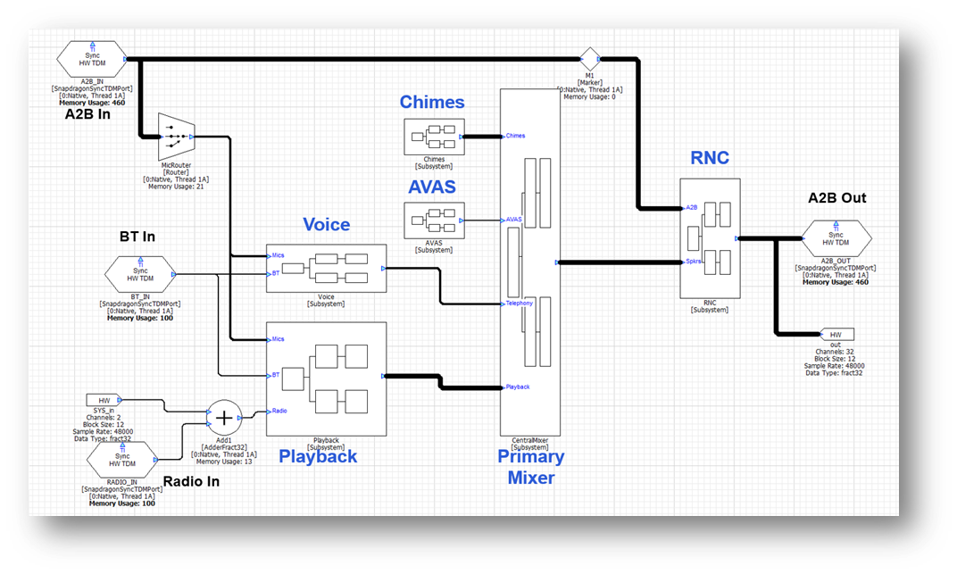
All other features, like playback processing and telephony, are less sensitive to startup time and I/O latency and can be dealt with later. An example top-level signal flow is shown below and we will highlight design decisions in the discussion below.
Early Audio
In the Gen 5 platform, DSP0 is designated for early audio and boots first. All early audio features must exist on this core. The early audio features must be developed using the standard modules which ship in the AWE-Q BSP. This is because custom modules cannot be loaded until the Arm has booted. Early audio also has access to 10 MB of data in total which is used to store the signal flow and WAV files used for chimes players. Given these restrictions, we recommend that you keep early audio features to the minimum required to support regulatory requirements like chimes.
Another requirement is that the Synchronous Master TDM port must be on DSP0 and part of early audio. All other TDM devices are allocated later and look to the SM port to synchronize their clocking. Given these restrictions, the processing is partitioned as follows between the cores:
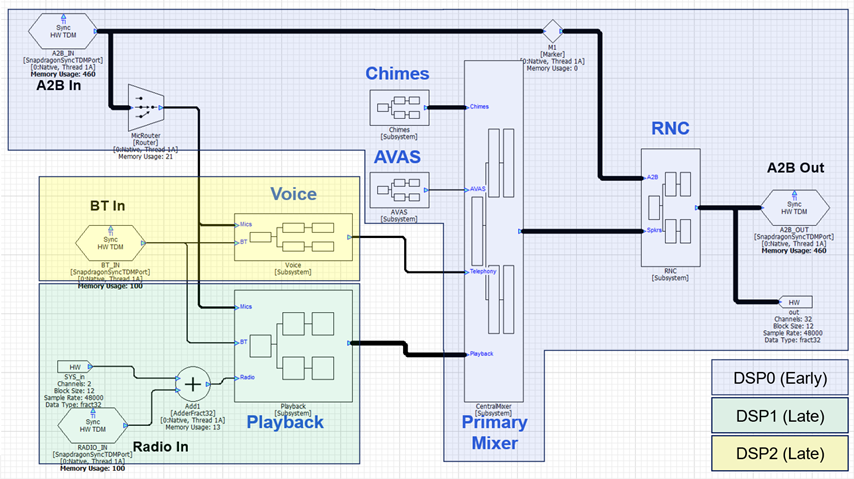
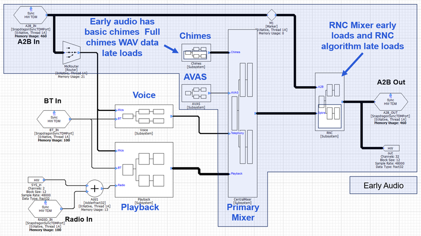
The RNC algorithm will most likely be custom IP and not included in the module set available during early audio. This needs to be late loaded and would be accomplished using a Subcanvas inside of the RNC subsystem. The chimes processing will be segregated into “Early Chimes” with WAV files in the 10 MB flash partition and “Late Chimes” which have access to more data from the HLOS. The data for Late Chimes will be loaded via a Shared Memory Mapper module. The early audio processing with these 2 carve outs is shown below.
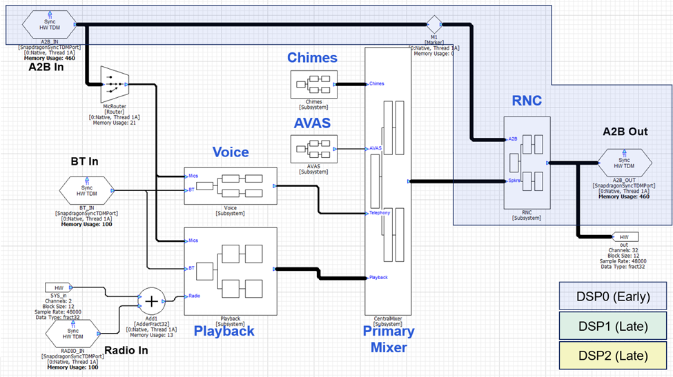
Low Latency
Next lay out the low latency signal path. Which TDM port(s) receives microphones and sensors, and which one(s) drives the loudspeakers? In the design above, we assume that the system uses an A2B network for inputs (sensors and microphones) and outputs (loudspeakers) and that this is the same set of speakers used for early audio. The RNC algorithm will be placed between these TDM ports and in order to minimize latency, the RNC algorithm should also be on DSP0. As mentioned above, we expect that the RNC algorithm will use custom modules, and the algorithm would be late loaded using a Subcanvas. The RNC Subsystem would also have a final mixer that would combine RNC and playback signals. With this design, the low latency signal path is shown below:
Subcanvases and Late Loading of Features
Subcanvases are a new Audio Weaver introduced in the 2025.2 release and available in AWE-Q starting in the R4.3 release. A Subcanvas module encapsulates an entire AWD systemas a single module. This provides many advantages especially for large automotive systems:
Allows large systems to be subdivided into individual features which can be developed by separate teams and combined by a System Integrator.
Speeds up early loading of audio systems. Audio features in a Subcanvas can be late loaded if they are not needed during the early boot phase. Primary targets are RNC, Telephony, and Playback processing.
Supports late loading of custom modules (via dynamic libraries) on early audio cores.
Easily incorporate 3rd party IP. IP is encrypted and the internal details are hidden.
The IP may be fully tuned by the IP developer using a new feature called message “tunneling”.
IP may be switched out at run-time. The system inside of the Subcanvas can be destroyed and reloaded while the overall signal flow is running. This simplifies software updates and supports downloadable audio features.
It is recommended that the main audio features (playback, AVAS, chimes, telephony, etc.) each be contained in a Subcanvas. The Subcanvas exposes one control array for setting of parameters and a second control array (if needed) for getting of parameters. This follows our best practices for system control. The Subcanvas should not contain any I/O modules (such as TDM or ALSA I/O). It is best if these are part of the outer signal flow and configured by person responsible for overall audio feature integration. The processing inside of a Subcanvas can be multi-threaded but can only run on a single instance (core) of the system.
There are also supporting modules, similar to ParamSet, which can set and get internal module values based on signals in the upper-level system. The Subcanvas author specifies which modules and variables should be exposed for external control. Internal variables can be set using ParamSet-like modules and also through the AWE Manager control API.
A Subcanvas is released using the same Generate Target Files dialog that is used for top-level system control. The internal details of the Subcanvas are described by a Container file (AWC) and it is almost identical to the Container file that was described earlier.
TDM Ports, Threads, IPC, and Latency
It is important to understand the input to output latency of your signal flow. This is crucial for latency sensitive algorithms like RNC and telephony, and also important to track for playback algorithms that require time aligned signals. The latency in your signal flow comes from 3 sources: I/O latency, changing threads and cores, and algorithmic latency. A full explanation is provided in the Audio Weaver Architecture Document, and we provide basic information here.
I/O Latency
The Synchronous TDM Port module uses DMA and double buffering. The latency for an input or output port equals 1 block size. Using a TDM port for input and then another TDM port for output adds a total of 2 x block size latency.
Analog Latency
This is the latency through the codecs and audio networks (like A2B or Ethernet) in the system. Refer to the datasheets for your devices to understand the specific latencies.
Changing Threads and Cores
The ChangeThread module sends audio to another thread on the Snapdragon. This thread can be on the same core or on a different core. If the block size does not change, then the latency through the ChangeThread module equals 1 block size.
The ChangeThread module is able to change the block size at the same time as changing the thread or core. In this case, the latency equals the larger of the input or output block size.
Algorithmic Latency
The final latency component is due to the specific modules that are in your signal flow. The vast number of modules in Audio Weaver do not introduce any latency. Examples of zero latency modules are Scalers, Mixers, Routers, Adders, etc. Other modules, like Delays or FIR filters, introduce latency based on their settings.
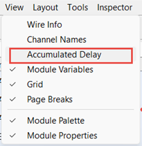
Audio Weaver can display the accumulated latency from the input pin to a specific point in the signal flow. To enable this, select View-->Accumulated Delay in the menu.
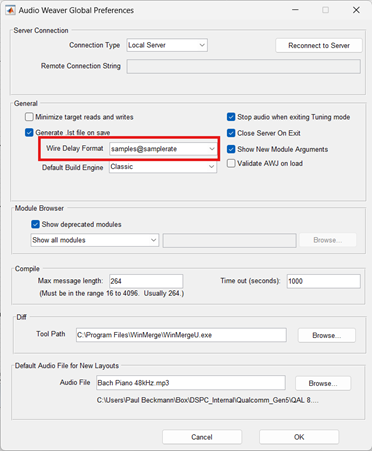
The latency will then be shown and updated whenever you build the system or redraw it. The latency can be shown in either units of samples or milliseconds. This is set on the Global Preferences dialog as shown below:
Audio Weaver is able to track the algorithmic latency and the threading latency. The I/O latency and Analog Latency are not included.
Latency Examples
Here are some specific examples to help you understand the principles. A Scaler module will be used to illustrate zero latency modules and a DelayMsec module will be used to illustrate modules which add latency.
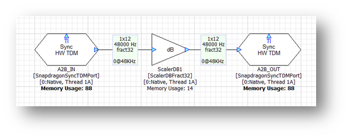
Basic I/O
This system operates at a block size of 12 samples at 48 kHz. The only module is a Scaler which introduces no latency. The accumulated latency is shown in samples and is zero at the output TDM port. The I/O latency comes from the BSP code and is not shown in the signal flow. However, it will be 2 x 12 samples = 24 samples. At 48 kHz, the total digital latency is 0.5 msec.
In general, the digital I/O latency through Audio Weaver equals 2 times the block size. On top of this, you need to consider additional latency of A2B and analog I/O. For example, on the SA8255 ADP, the analog latency is 1.1 msec. If you measure the total analog input à analog latencies, you will observe:
Block Size (samples) | Total latency (msec) |
8 | 1.43 |
12 | 1.6 |
16 | 1.76 |
24 | 2.1 |
Algorithmic Latency
Now add a Delay module set to 96 samples. The signal flow now shows:
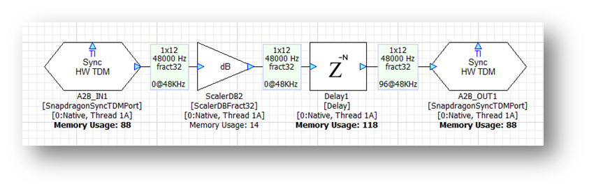
The total digital latency is 96 samples + I/O latency = 120 samples. Although smaller block sizes achieve lower latencies, they come at the cost of higher CPU load. We recommend using the largest block size possible.
Another restriction in the R4.3 release of Audio Weaver is that all synchronous TDM ports must operate at the same block size and sample rate.
ChangeThread Latency
Changing cores and threads in your signal flow adds additional latency. It doesn’t matter if you are switching cores or threads, the latency is always the same and equals 1 block size. If you have a latency sensitive algorithm, then you should keep it on the same core – and same thread – as the TDM ports handling the low latency I/O.
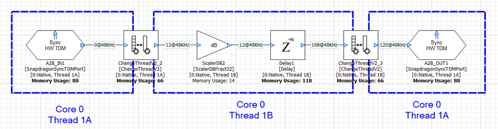
In the first example, we leverage 2 threads on Core 0 to increase the amount of processing power available. The first ChangeThread modules sends audio from thread 1A to thread 1B. The second ChangeThread module sends the data back to thread 1A. Each ChangeThread module adds 12 samples of latency and Audio Weaver shows the total latency as 120 samples (96 samples of delay + 2 x 12 from ChangeThread).
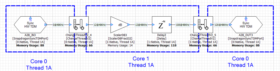
With a slight adjustment, the ChangeThread module can be configured to send data from Core 0 thread 1A to Core 1 thread 1A. This is shown below and the total latency is still 120 samples. Sending data between cores and threads in Audio Weaver adds the same amount of latency.
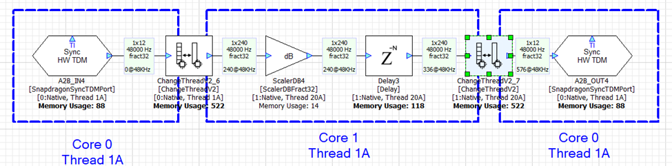
In the next example, we keep Core 0 working at a 12 sample block size and configure Core 1 to use a 240 sample block size. The ChangeThread module handles the buffering up (12-->240) and the buffering down (240-->12). Each ChangeThread operation now adds 240 samples of latency and the total latency is 576 samples.
Parameter Control
This section describes the basics of parameter control in AWE-Q. AWE-Q allows applications to Set and Get parameter values within the Audio Weaver signal chain. This is a fairly low-level API and the OEM or Tier 1 developing the overall system needs to still write an Audio Manager which coordinates all of the functions.
Audio Manager
You can think of the Audio Manager as the “conductor” that coordinates all of the audio functions to yield a pleasing audio experience. Here are some examples of the functions of the Audio Manager:
Driver receives a call: Audio Manager pauses media playback, routes call audio to front speakers, and mutes navigation.
Navigation speaks: It "ducks" (lowers) the music volume briefly to make the navigation prompt intelligible.
Audio system is started. Audio Manager restores previous volume settings and ensures that it is not too loud or too soft.
AI wake word detected: ducks the music and wakes for the full query. Then plays back the response in the zone that the request originated in.
The Audio Manager is part of the OEM’s brand and is outside the scope of AWE-Q. This section focuses on AWE-Q’s parameter control API which is called by the Audio Manager to enable these experiences.
Audio Weaver Control Basics
Audio Weaver parameter control is based upon a number of core principles:
The Audio Weaver control APIs are designed to write to directly to module instance variables. You can write to scalar variables or to array variables. Updates are made one variable at a time.
All variable data types are 32-bits long. Modules can use float, int, uint, and fract32 data types.
Modules are identified on the target based on their objectID. Each module has a unique objectID which is set in Designer.
Variables within a module are identified based on their offset from the start of the module instance structure. The combination of objectID and variable offset uniquely identifies where in memory a variable is located.
Using the Generate Target Files feature in Designer, you can generate a Container file which contains the objectIDs and offsets of all tunable module variables. For each tunable variable, Designer additionally generates a HANDLE which encodes the objectID, offset, coreID, and whether the variable is a scalar or an array.
The Container file also contains information about the data type and range of each variable.
The Container also contains the length of arrays and the Audio Weaver APIs throw an error if you read or write outside of array bounds.
Audio Weaver does not distinguish between controlling modules during a tuning session (when connected to the Designer PC tools) and controlling modules at run-time in the final deployed system. Similar concepts and APIs are used in both cases.
Assigning objectIDs
You assign objectIDs in Designer by right-cliking on a module and selecting ObjectIDsàAssign. Alternatively, you can enter an objectID in the module’s Property View.
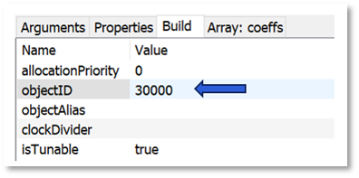
By default, the field “objectID” is empty and the objectID will be automatically assigned when the system is built. (Wires, modules, and layouts are all assigned objectIDs at build time. They are sequentially numbered starting at 1.) If you want to control the module at run-time, then you must assign a custom objectID. Custom objectIDs are in the range 30000 to 32767.
Modules that have custom objectID assigned are drawn in bold in Designer.
Generating Target Files
After you have assigned objectIDs in your system, you generate the Container file which is used by AWE Target Configurator utility. Go to the ToolsàGenerate Target Files menu item in Designer. It will open the dialog shown below. Use the “Container Setting” panel on the right-hand side and generate a “Toplevel” container.
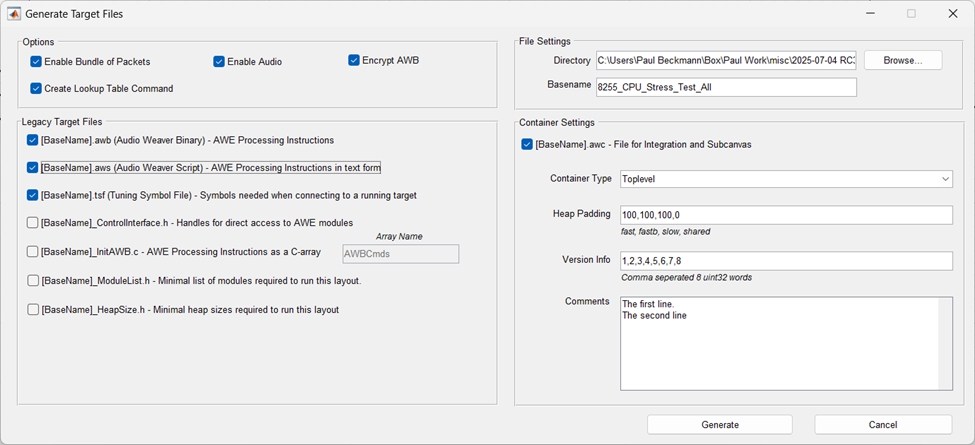
The Container file has an AWC extension and internally uses a JSON format. The AWC file contains:
Version information / Comments / Build date and time
Heap sizes used by your design
Details on the layouts (threads) used
Input and output device details
A list of module classes used
Information on all tunable modules and variables
Binary AWB contents. This can optionally be encrypted
The AWC file is used as input to the AWE Target Configurator. AWETC generates a binary file which is used on the target and includes all tuning information.
Best Practices Using Control Arrays
A typical automotive system has 20 to 30 modules which need to be controlled at run-time. One possible approach to designing the control interface is to assign objectIDs to each of these modules and generating the container file as discussed above. This is a fine approach, but the main downside is that every time you change your control API, you’ll need to generate the container and rebuild the Audio Manager on the HLOS.
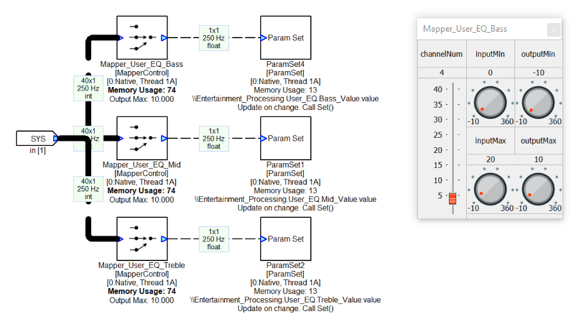
An alternate approach is to aggregate all controllable parameters into a single SourceInt module. This module holds an array of N values and has an objectID assigned to it. Then, individual values are extracted from this array and written into specific module variables using the MapperControl and ParamSet modules. The advantage of this approach is that you would have to expose only a single objectID and can make changes to the control code via changes to the Audio Weaver signal flow. Plus, if your design has 40 tunable variables, oversize the control array to 50 values. This gives you expansion in the future. This is the recommended approach when controlling large signal flows, like automotive systems.
An example of using a control array is shown in the figure below. This shows a portion of the top-level system and you’ll notice that there is a SourceInt module called “Control_IPC_In” to which the HLOS writes and a SinkInt module called “Control-IPC_Out” that can be read by the HLOS.
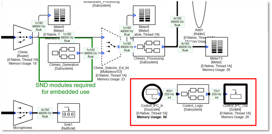
Inside the Control_Logic subsystem are multiple ParamSet modules which write into various modules. For example, the control array has 3 values for controlling the Bass, Mid, and Treble tone controls. The MapperControl module extracts one of the 3 values (channelNum as shown on the inspector), clips input values to the range [0 20], and then remaps linearly to the dB range of [-10 +10]. This is then fed into a ParamSet module which writes the value into another module.
Implementing Chimes
This section provides recommended approaches for implementing chimes players on the AWE-Q platform. It covers specific topics connected to AWE-Q and you can find other generic documentation on DSP Concepts publicly facing Doc Hub.
Available Modules
Audio Weaver’s WAV players are part of the Sound Design Module Pack. These modules are included as part of AWE-Q and found in the Module browser under “Sound Design”.
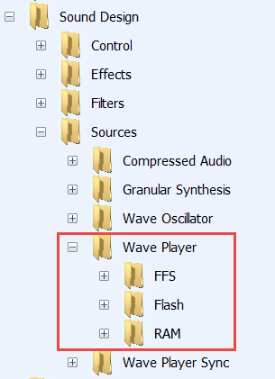
There are 3 types of WAV players:
RAM - The WAV data is stored in Audio Weaver heap memory. The WAV data is located on the PC and the samples are included in the AWB file. This data is available during early boot.
Flash - The WAV data is part of the “Flash File System” which is included in awe_config.bin. The WaveLibraryGenerator tool from DSP Concepts is used aggregate files (and a directory) in a binary file. This binary file is specified in awecore.yml and the AWE Target Configurator (awetc) tool pulls this data into the awe_config.bin file. This data is available during early boot.
FFS - This is only for advanced users. Instead of a single system wide Flash File System, these modules allow you to define multiple file systems that are loaded by the HLOS. These file systems store data in RAM. This feature is not recommended for early chimes but only for late chimes.
For AWE-Q, we recommend using the “Flash” players since they are available during early boot and do not consume heap memory.
For each category of WAV player, there are 4 variants:
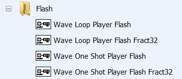
The “One Shot Player” plays the WAV data once and stops. The “Loop Player” continuously plays the WAV file and loops from end back to the start. The Loop Players are typically used for engine sound generation.
There are also floating-point and fixed-point (Fract32) variants of each player. For AWE-Q, you should use the floating-point players since most signal flow manipulation occurs with other floating-point modules. In summary, you should use the “Wave Loop Player Flash” and “Wave One Shot Player Flash” modules in your design.
Chimes Example
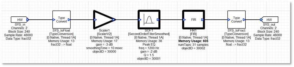
The file Chimes.awj has an example chimes subsystem. It operates at a 48 kHz sample rate with a block size of 240 samples. It is designed to be incorporated into an overall automotive system as a Subcanvas. The top-level system has these modules:
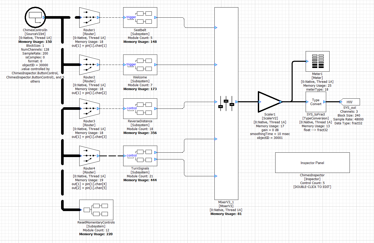
The system includes 4 subsystems for playing seatbeat warning chimes, a welcome sound, park distance chimes, and turn signal chimes. Inside each of these subsystems is a Wave One Shot Player Flash and multiple modules for controlling the wave player. For example, inside the Seatbelt subsystem, you’ll find:
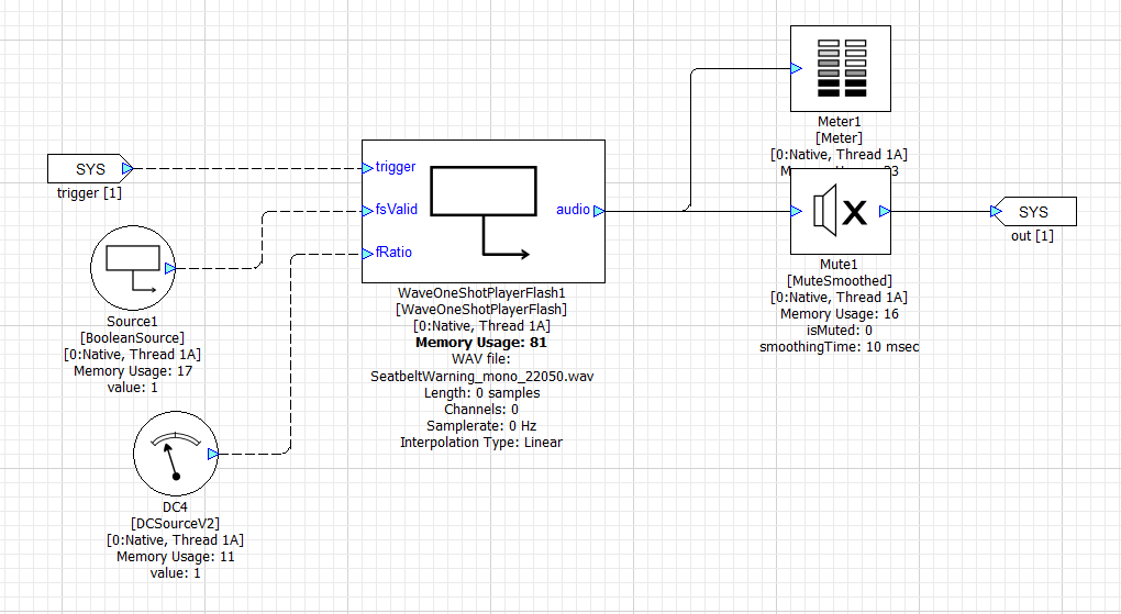
The Wave Player arguments specify the name of the file to play and the output block size and sample rate:
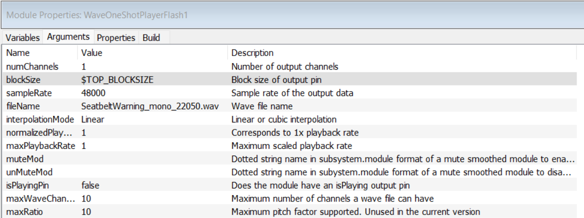
In Native mode, the file to play is found using Designer’s File Search Path. On the Snapdragon target, the file to play is found inside the Flash File System.
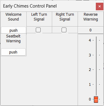
All of the chimes players are controlled via the module ChimesControlIn. This is a SourceV2Int module and holds an array of 128 int32 values. In this example, only the first 5 values are used while the remaining 123 values are for future expansion. The 5 control values are:
Index | Type of Control | Purpose |
|---|---|---|
0 | Momentary | Triggers seat belt chime |
1 | Momentary | Triggers welcome sound |
2 | Integer value. 0 to 4 | Park distance control 0 = Off 1 to 4. Increasing beep speed. |
3 | On / off toggle | Plays left blinker sound |
4 | On / off toggle | Plays right blinker sound |
The first two controls are “Momentary” controls. When the control code writes a value of 1 it triggers the corresponding chime player. Modules inside the “ResetMomentaryControls” subsystem reset the “1” values back to “0”; the control code does not need to do this.
The last 2 controls are “on / off toggles”. The control code writes a “1” value and this starts the blinker sound. The blinker will continue playing until the control code writes a “0” value.
The ChimesControlIn array is used during early chimes and late chimes. During early chimes, the Hexagon BSP code receives control messages from the SAIL subsystem. These messages control an integer payload which is written to the start of the ChimesControlIn array. After the HLOS system has booted, the Hexagon BSP disables messages from the SAIL subsystem and the OEM audio manager takes over chimes control by writing into the same ChimesControlIn array.
The Audio Weaver example includes a Subsystem Inspector which writes values into the ChimesControlIn array. This allows you to trigger chimes via the Designer GUI during development.
WaveLibraryGenerator
If you look inside all 4 subsystems, you will see that the wave players reference these 4 files:
SeatbeltWarning_mono_22050.wav
Welcomesound_22050.wav
ReverseWarning.wav
TurnSignal.wav
Run the WaveFileGenerator utility and include these 4 files. The order you add them is not important since the files are reference based on their names and not their indexes. Give it a name (“early_chimes.bin”) and click Generate.
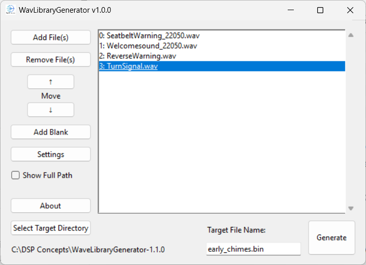
This will generate 3 output files:
early_chimes.bin - binary blob containing the file system. This has the file names and the file contents.
early_chimes.txt - text file listing the files included in early_chimes.bin. For documentation purposes.
early_chimes.csv - file names in a binary format that can be used by advanced users to switch out WAV files at run-time.
Adding Wave Files in AWETC
The next step is to configure and run AWE Target Configurator. Edit the file awecore.yml and update the Flash File System portion as shown below:
flash_file_system: source_file: ../../../WAV/early_chimes.bin
Set the source_file path based on your directory structure. Now run awetc and generate the deployment files. Push the deployment files to your target and reboot the system.
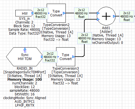
Next connect the Audio Weaver Server to the target. Since the target now has a Flash File System, the Flash-->Flash Manager menu item will be available.
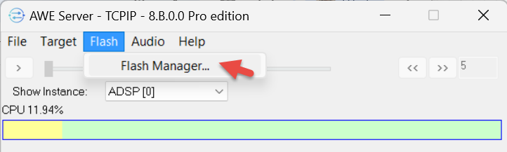
Here you will see the 4 files that you added:
Now that the flash file system is configured, the WAV players can generate sound even during the early boot phase.
Automotive Signal Flow Walk-Through
This section does a detailed review of the reference automotive audio system (TBD.awd) that is provided with AWE-Q. The system is designed for the 8255 but will run with slight changes on the 8797.
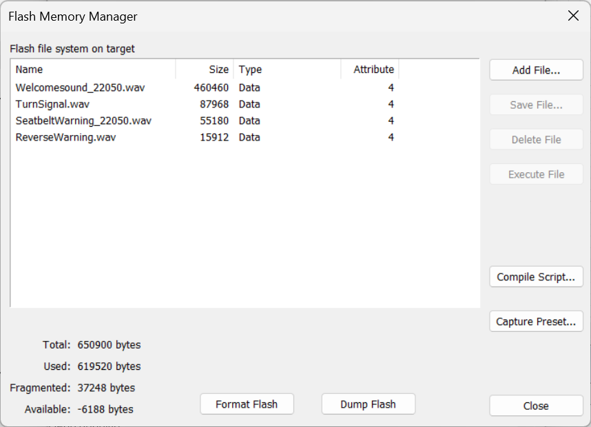
The main low-latency path is from the A2B_IN TDM port to the A2B_OUT TDM port. These are synchronous TDM ports that share the same clock and are configured for a 12 sample block size. The output device is the Synchronous Master and generates the main audio clock for the system. The output wire also connects to the Audio Weaver hardware output pin and this enables audio output in Native mode (during PC simulations).
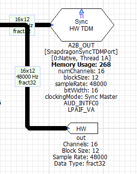
The Synchronous Master TDM port must be located on instance 0. The matching input TDM port is configured as a Synchronous Aligned device and it is assumed that the input and output ports have hardware wiring which shares the bit clock and word clock.
These ports are configured with a block size of 12 samples and operate at 48 kHz. This leads to a fundamental block size of 0.25 msec and all other audio threads in the system must be a multiple of 0.25 msec. We have chosen to run the other use cases (Chimes, AVAS, Playback, and Telephony) at a 5 msec block size. These block sizes are fully configurable in the Designer GUI and can be modified if you have other requirements.
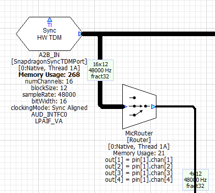
In our design, all of the TDM ports are located at the top-level. BT_IN is the TDM port which receives Bluetooth audio and RADIO_IN is the TDM port that receives audio from the tuner. Both of these ports are configured for 12 sample I/O to match the Synchronous Master port (this is required in R4.3). This audio data is converted to a 240 sample block size within the Playback and Voice subsystems.
All of the serial ports are also located on the same thread and core (1A0). This is done on purpose because all serial ports on the Snapdragon access the same DMA memory. Putting the TDM ports in layout 1A0 forces them to execute sequentially and this leads to the most efficient processor utilization. If they are in separate threads and executing simultaneously, then the ports will stall waiting for DMA memory access.
The design adds the HW input pin to the radio source. This is to enable easier evaluation of the playback processing during Native mode processing. If your focus is on RNC, you might want to move the HW input pin to the A2B input.
RNC Processing
Chimes
This feature is implemented by the Subsystem shown below. The Subsystem outputs 5 channels of audio corresponding to the vehicle positions: left front, right front, center front, left rear, and right rear (just like a 5 channel home theater setup).
The early chimes are generated by the Subcanvas “ChimesSC” using flash WAV players. This processing was described early in this section. ChimesSC outputs 3 front channels
The Subcanvas “ChimesSC” implements early chimes using the flash WAV players (this was described above).
AVAS
The feature generates synthetic engine sounds and is mandated for electric vehicles. In our design, the AVAS Subsystem contains the modules shown below. There are two main components. The first portion is the Subcanvas “AVAS_SC” which is controlled via a 6 element array. These are floating-point values and represent:
Index | Purpose |
|---|---|
0 | Accelerator pedal position in the range [-50 +50] |
1 | Vehicle speed in km/h |
2 | Torque |
3 | RPM |
4 | Vehicle ready. Boolean value. |
5 | Drive motor code (not used) |
These values are transferred to the “AVAS_SC” Subcanvas using the SubcanvasArraySet module.
The second component is a “DriveSimulator” subsystem which simulates vehicle motion. The only purpose is to enable simple demos using a single “Pedal Position” slider. A simple custom inspector panel allows you to test the AVAS function in simulation.
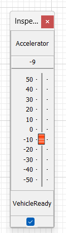
The AVAS processing is single threaded and occurs at a 5 msec block size at a 48 kHz sample rate. All Subcanvases require both input and output pins. Technically, the AVAS function does not require an audio input, but we have used a dummy mono input to satisfy the input requirement.
The design file AVAS.awj was used to generate the AVAS.awc container file. Looking at the design file, you will see that the left portion contains the control logic and the right portion implements the sound generation. The AVAS subsystem also contains a DriveSimulator for simplified development and demoing.
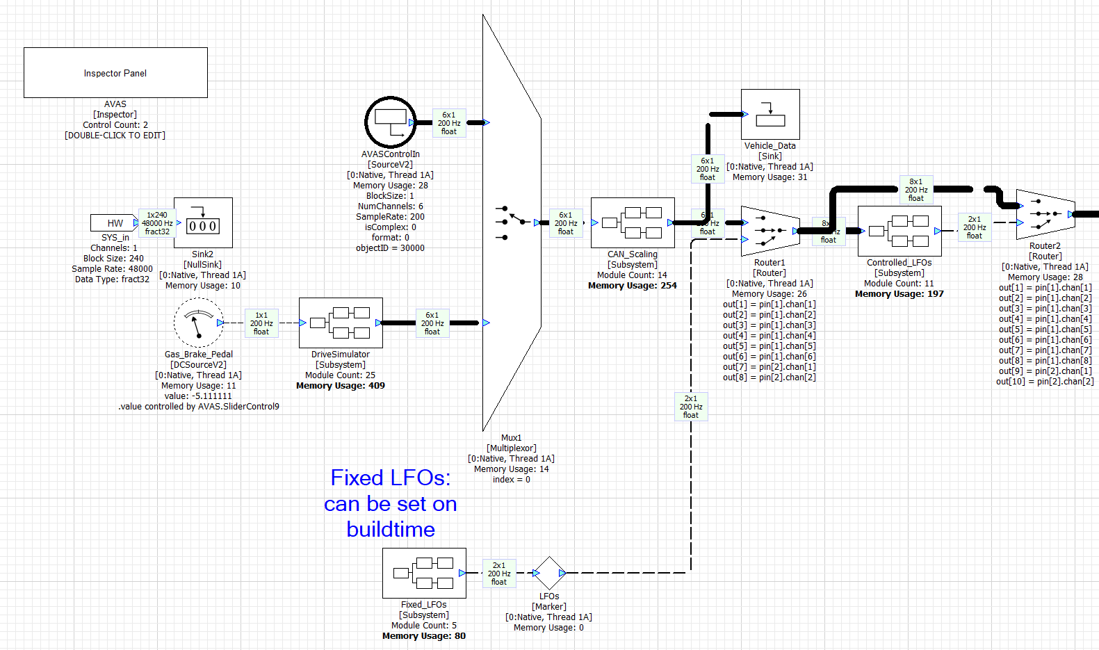
The 6 floating-point control values are written to the array AVASControlIn and these feed the rest of the algorithm.
The main WAV players are in the WavePlayer subsystem. It contains 6 WAV players each playing back a different sound with looping.
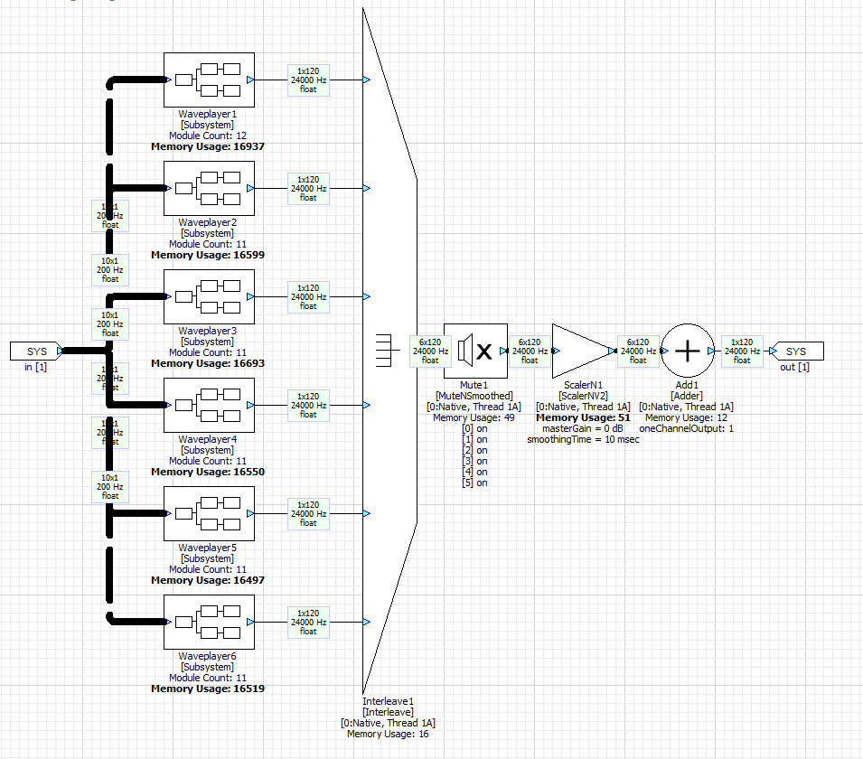
Looking inside Waveplayer1 you will see that it contains a looping flash WAV player followed by a Scaler which applies gain. Each of the 6 WAV players is active only over a portion of the RPM range.
The WAV players are all configured for 24 kHz operation. 5 msec equals 120 samples. Higher sample rates are not needed because engine sounds are lower in frequency. After the WAV players there are several more stages of processing: mixing, nonlinear distortion, channel gains, and finally and interpolator to convert the 24 kHz to 48 kHz.