Oversampling Peak Detection Example
A digital audio signal contains samples of the underlying analog wave form. Although the digital samples may form an accurate representation of the signal, the digital samples may miss some behavior of the analog signal between samples values. This can usually be ignored but it can be important if the signal is to be output to a DAC. Consider the waveform shown below.
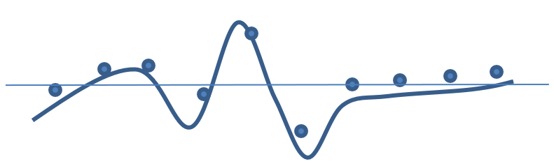
If only the digital sample values are seen, the true peak is missed and it is possible for this signal to clip when converted to analog. The analog signal is exceeding the allowable range, and can harm the playback system.
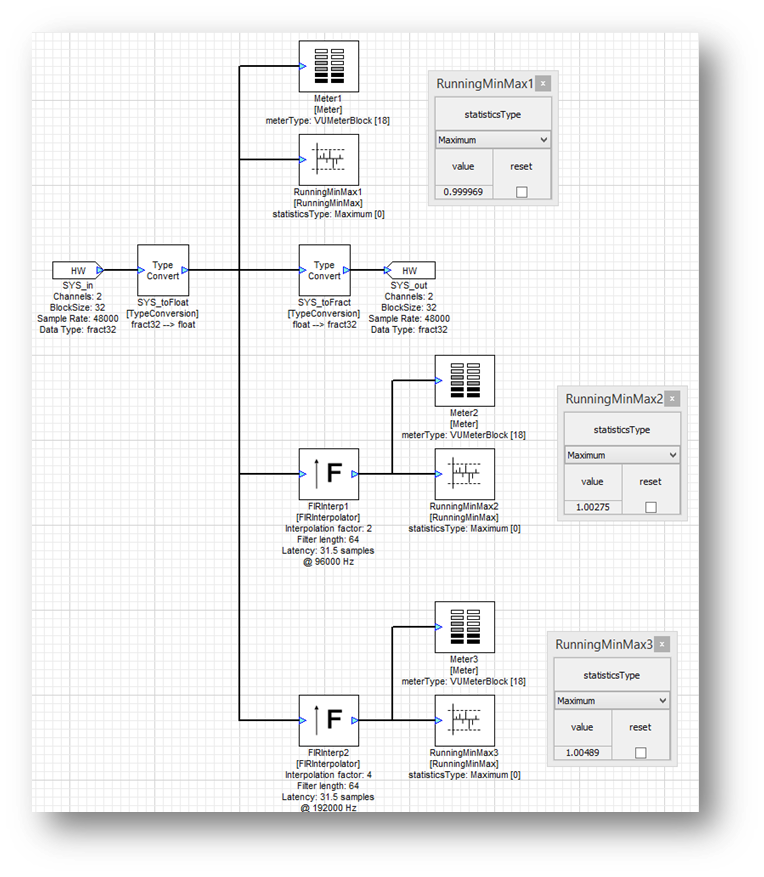
In order to prevent this, first see what is happening between samples. This can be accomplished using oversampling together with a RunningMinMax module. Oversampling is used in the layout below by factors of 2 and 4 using the FIRInterpolator module. The RunningMinMax module is used to compare the sample value in the original 44.1 kHz waveform against the peak found in the 88.2 kHz and 176.4 kHz oversampled signals.
Missing the peak only occurs if there is high frequency content in the signal; something with cymbals is ideal. In our test, a piece of processed pop music was played. The peak value in the 44.1 kHz signal is 0.999969 – basically full scale. The true peak is actually 1.00489, or 0.042 dB. To prevent digital clipping of the analog waveform reduce the signal level by this amount or set the limiter threshold 0.042 dB lower.