
TWS Reference Design
About This Application Note
The TWS Reference Design Application Note describes the DSP Concepts True Wireless Stereo (TWS) reference design. The Audio Weaver Design, intended for use with DSP Concepts TWS RAPID Kit, features standard processing and signal flows seen in popular TWS commercial products. For an in-depth explanation of the RAPID TWS Kit and how to set up your kit, please refer to the RAPID TWS Kit Native Mode Setup and User Guide and the TWS_Audio-Weaver--RT685EVK-RevE-Board-Users-Guide.
Processing Overview
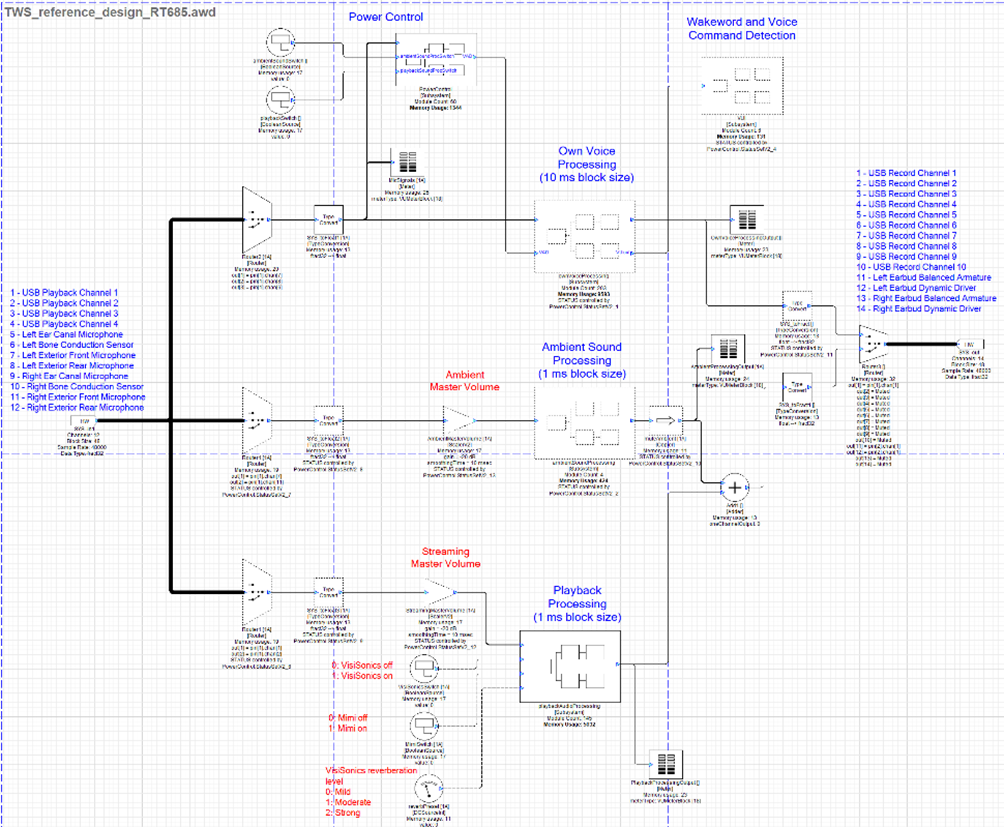
Audio in the design can be broken into three distinct, but related paths. One is the path of audio from the microphones to the connected device called the own voice processing path. The second is the path of audio from the device to the transducers in the earbuds called the playback processing path. The third is the path from the microphones to the transducers in the earbuds called the ambient sound processing path. The following diagram outlines the three paths.
The processing that composes these paths is described later in this guide.
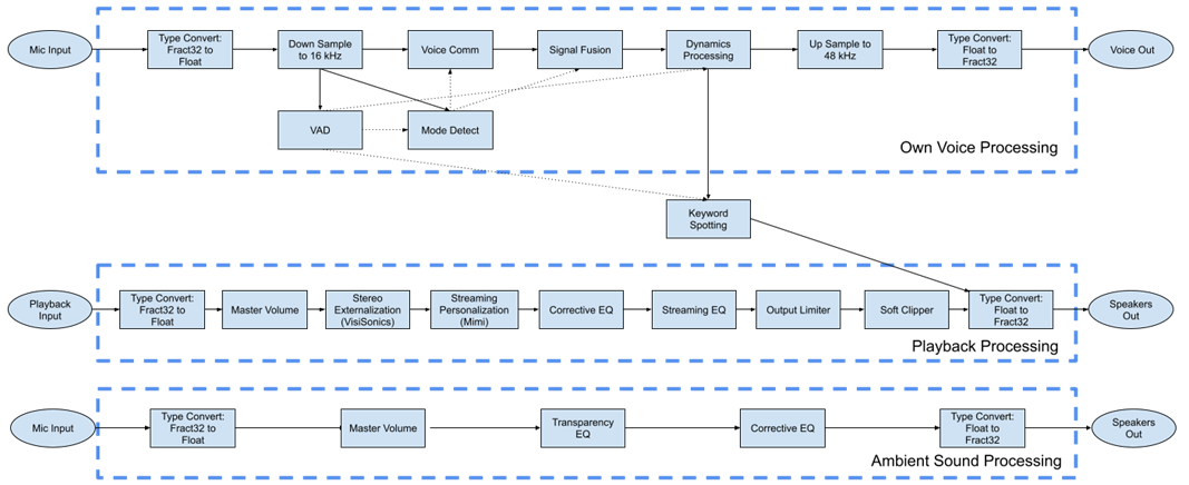
TWS Reference Design High-Level Processing Diagram
Own Voice Processing Path
This section describes the major components of the own voice processing path.
Voice Activity Detection
The Voice Activity Detection (VAD) subsystem utilizes the bone conduction sensor in the RAPID earbuds to detect when the user is speaking. The status of the VAD is propagated to Mode Detection, Dynamics Processing, and Keyword Spotting to affect the processing they apply.
Mode Detect
The mode detection (Mode Detect) subsystem is used to detect the noise conditions under which the device is operating. This status is propagated to the Voice Communication and Signal Fusion subsystems to affect the processing they apply. The set of states that are possible are low noise, high noise, and wind. The status is encoded as a number as described in the following table.
Table: Mode Detect Codes
Mode Detect Code | Status |
|---|---|
0 | Low Noise |
1 | High Noise |
2 | Wind |
Voice Comm
The Voice Communication (Voice Comm) subsystem applies processing to the incoming microphone signals to improve the quality of speech that is transmitted to the connected device. The processing applied depends on what noise condition is detected by the mode detect module. The possible modes of operation are low noise, high noise, and wind. In low noise and high noise mode, beamforming is used to reject noise outside of the path from the microphones to the mouth. In wind mode, processing is applied to remove as much wind noise as possible from the forward microphone in the earbud. The output of all processing modes is then fed to single channel noise reduction (SCNR).
Signal Fusion
The Signal Fusion subsystem combines the bone conduction sensor with the forward-facing microphone under wind conditions. Under other modes, the signal is left unaltered by the subsystem.
Dynamics Processing
The dynamic processing system contains all dynamic processing applied to the own voice processing path signal. The system consists of a noise gate keyed to the VAD, transient shaping, automatic gain control (AGC), and peak limiting.
Keyword Spotting
Keyword spotting is a basic demonstration of Voice User Interface (VUI) and Voice Assistants (VAs). It is composed of the Sensory™ TrulyHandsfree™ module and a One Shot Player module. The Sensory module listens for the desired keyword. When the keyword is detected, it triggers the One Shot Player module to play a short recording of a bell into the playback processing path of the design. The functionality of this system can be extended for more advanced VUI/VAs functionality.
Playback Processing Path
This section describes the major components of the playback processing path.
Playback Master Volume
The playback master volume is a playback volume control. The other gains are fixed and not to be changed.
Stereo Externalization (VisiSonics)
Stereo Externalization prevents in-head localization by making stereo streaming audio content sound like it originates from loudspeakers in front of the user. Users can adjust the reverberation level using three presets.
Streaming Personalization (Mimi)
Streaming Personalization amplifies and changes the frequency response of streaming audio signals to optimize audio playback based on a user’s hearing ability and preferences. Users can adjust the processing using four age-based presets.
Corrective EQ
A corrective EQ is applied to the playback processing path to flatten the frequency response of the earbud drivers’ output at the eardrum reference point.
Streaming EQ
A streaming EQ is applied to the playback processing path to allow users to tune the spectral quality of streaming audio content for an enhanced listening experience.
Output Limiter
The output limiter subsystem is a peak limiter used to keep the system from clipping.
Soft Clipper
The soft clipper protects the earbuds from potentially damaging peaks in the signal.
Ambient Sound Processing Path
This section describes the major components of the ambient sound processing path.
Ambient Sound Master Volume
The ambient sound master volume is an ambient sound volume control. The other gains are fixed and not to be changed.
Transparency EQ
A transparency EQ is applied to the ambient sound processing path to match the frequency response of the external microphone input signal to the frequency response of an open ear at the eardrums.
Corrective EQ
A corrective EQ is applied to the ambient sound processing path to flatten the frequency response of the balanced armature driver’s output at the eardrum reference point.
Power Control (RT685 Only)
The power control feature is only available in the RT685 version of the reference design. It includes APIs to activate and deactivate playback processing and ambient sound processing. Always on features, including own voice processing and keyword spotting, are automatically activated or deactivated by the following elements.
Quiescent Sound Detector
The Quiescent Sound Detector (QSD) module monitors activity in the ambient sound level. If it detects a quiet ambient sound level, the power control will deactivate all processing other than the QSD.
Voice Activity Detection
The Voice Activity Detection (VAD) subsystem utilizes the bone conduction sensor in the RAPID earbuds to detect when the user is speaking. If the QSD detects sounds, it will activate the VAD. If the VAD detects that the user is speaking, it will activate all own voice processing and keyword spotting. The status of the VAD is propagated to Mode Detection, Dynamics Processing, and Keyword Spotting to affect the processing they apply.
Native Design
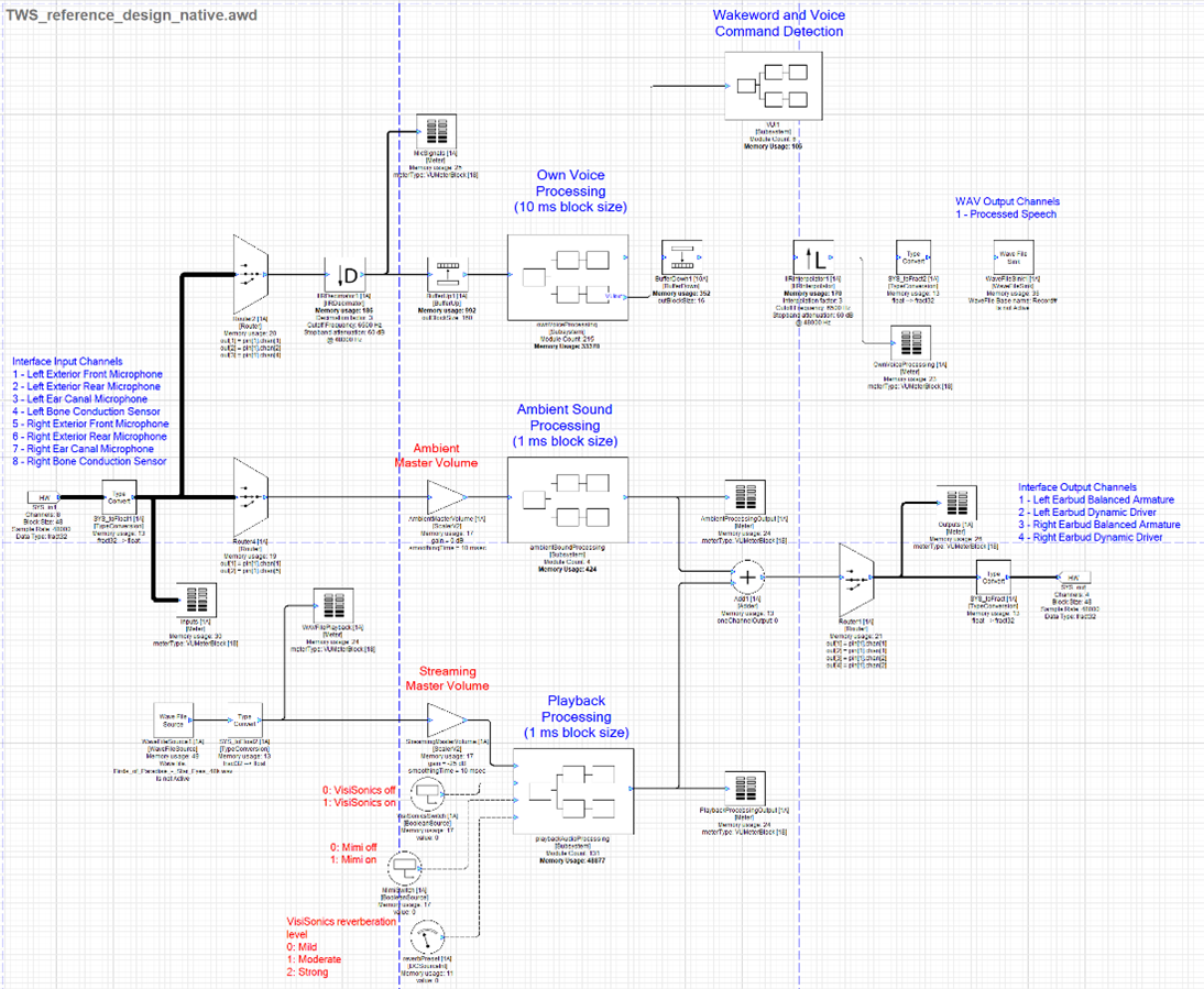
Native Mode TWS Reference Design
Setup
The native design assumes that you have followed the setup instructions in the RAPID TWS Kit Setup and User Guide. Please review that document before proceeding.
Calibration
Because the interface does not apply fixed gain to the signals from the earbuds, you must calibrate the gains applied to the microphones for proper functioning of the design. Levels should be set using the VU meter following the mic trim gain in the record path.
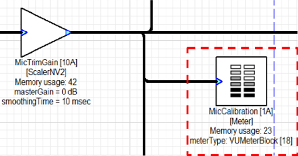
VU Meter
Exterior/Ear Canal Microphones
Play 1 kHz tone at 70 dBa at 1 foot from the transducer.
Adjust microphone gains via the ‘MicTrimGain’ ScalerNV2 module until they show -40 dBFS on the meter in Audio Weaver.
Bone Conduction Sensor
Wearing the earbuds, make an “E” sound at 70 dBc at 18 inches.
Adjust microphone gains via the ‘MicTrimGain’ ScalerNV2 module until they show -40 dBFS on the meter in Audio Weaver.
To roughly match microphone input and streaming output levels between Native and RT685 reference design, UMC1820 volume nob shall set as follows. After set the gain nob, they shall not be changed.
Microphone input
Microphone input analog gain knob shall be set to 12 o’clock direction.
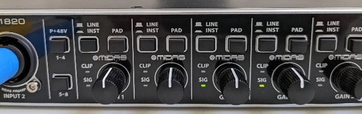
UMC1820 Microphone Gain Levels
Speaker Output
Speaker output analog gain knob shall be set to 10 o’clock direction.
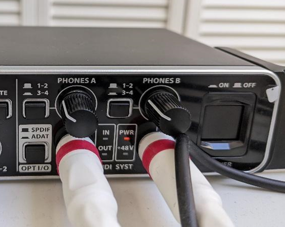
UMC1820 Playback Gain Levels
Signal Management
Audio Routing
In the native design, the input and output pins of the system are used for sending and receiving audio from the earbuds. The following tables display the configuration of signals assumed by the design. For setup instructions, refer to DSP Concepts RAPID TWS Kit Setup and User Guide.
Input
Table: Native Mode TWS Reference Design Input Channels
Pin | Signal |
IN 1 | Left Exterior Microphone #1 |
IN 2 | Left Exterior Microphone #2 |
IN 3 | Left Ear Canal Microphone |
IN 4 | Left Bone Conduction Sensor |
IN 5 | Right Exterior Microphone #1 |
IN 6 | Right Exterior Microphone #2 |
IN 7 | Right Ear Canal Microphone |
IN 8 | Right Bone Conduction Sensor |
Output
Table: Native Mode TWS Reference Design Output Channels
Pin | Signal |
OUT 1 | Left Earbud Balanced Armature |
OUT 2 | Left Earbud Dynamic Driver |
OUT 3 | Right Earbud Balanced Armature |
OUT 4 | Right Earbud Dynamic Driver |
Audio Playback
Playback of audio from a WAV file on disk is controlled by the Wave File Source module. Double left click the module to bring up an Inspector for the module. Playback can be stopped and started by clicking the isActive check box.
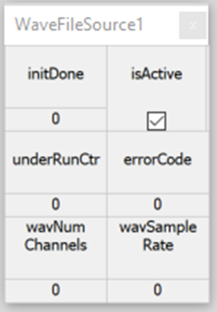
WaveFileSource Module Inspector
Control of the playback file path, number of channels, sample rate, block size, cache size, and looping can be accessed by completing the following steps:
Right click the WaveFileSource module.
Select View Properties.
Select the Arguments tab in the Property Sheet at the bottom of the Designer window.
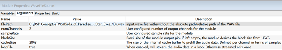
WaveFileSource Module Arguments Tab
Audio Capture
Recording of audio to a WAV file is controlled by the WaveFileSink module. Double left click the module to bring up a small Inspector control panel for the module. Recording can be stopped and started by toggling the isActive check box.
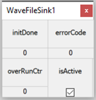
WaveFileSink Module Inspector
Control of the record file path, file base name, cache size, and bit depth can be accessed by completing the following steps:
Right click the WaveFileSink module.
Select View Properties
Select the Arguments tab in the Property Sheet at the bottom of the Designer window.
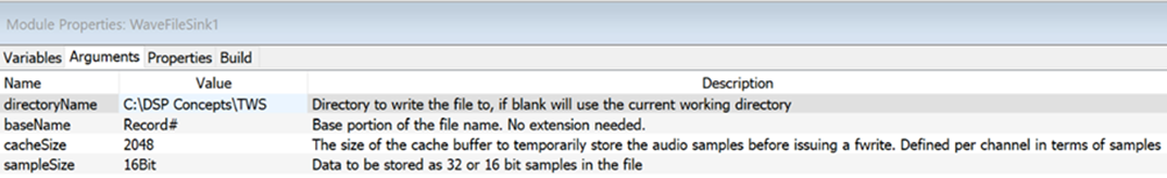
WaveFileSink Module Arguments Tab
Keyword Detection Model
You can access control of the trigger word recognition model file by completing the following steps:
Right click the SensoryTHF_V6 module in the VUI subsystem.
Select View Properties
Select the Arguments tab in the Property Sheet at the bottom of the Designer window.
Specify the file path of the desired Sensory model
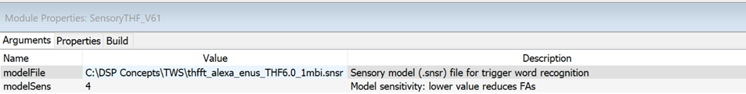
SensoryTHF_)V6 Module Arguments Tab
RT685 Design
RT685 TWS Reference Design
Setup
For instructions on how to use the RAPID TWS Prototyping Kit with an NXP® RT685 EVK, refer to the TWS_Audio-Weaver RT685EVK-RevE-Board-Users-Guide.
Signal Management
Audio Routing
In the RT685 design, the input and output pins of the system are used for all signals routed in and out of the design. The following tables display the configuration of signals used by the design. For setup instructions, including how to configure your Digital Audio Workstation (DAW), refer to the TWS_Audio-Weaver--RT685EVK-RevE-Board-Users-Guide.
Input
Table: RT685 TWS Reference Design Input Channels
Pin | Signal |
IN 1 | USB Playback Channel #1 |
IN 2 | USB Playback Channel #2 |
IN 3 | USB Playback Channel #3 |
IN 4 | USB Playback Channel #4 |
IN 5 | Left Ear Canal Microphone |
IN 6 | Left Bone Conduction Sensor |
IN 7 | Left Exterior Microphone #1 |
IN 8 | Left Exterior Microphone #2 |
IN 9 | Right Ear Canal Microphone |
IN 10 | Right Bone Conduction Sensor |
IN 11 | Right Exterior Microphone #1 |
IN 12 | Right Exterior Microphone #2 |
Output
Table: RT685 TWS Reference Design Output Channels
Pin | Signal |
OUT 1 | USB Record Channel #1 |
OUT 2 | USB Record Channel #2 |
OUT 3 | USB Record Channel #3 |
OUT 4 | USB Record Channel #4 |
OUT 5 | USB Record Channel #5 |
OUT 6 | USB Record Channel #6 |
OUT 7 | USB Record Channel #7 |
OUT 8 | USB Record Channel #8 |
OUT 9 | USB Record Channel #9 |
OUT 10 | USB Record Channel #10 |
OUT 11 | Left Earbud Balanced Armature |
OUT 12 | Left Earbud Dynamic Driver |
OUT 13 | Right Earbud Balanced Armature |
OUT 14 | Right Earbud Dynamic Driver |
Audio Playback
After you complete the instructions for setup in the TWS_Audio-Weaver--RT685EVK-RevE-Board-Users-Guide, the first four input channels of the design become available for routing audio from your DAW to the RT685 board. This is achieved by routing the output of audio tracks in your DAW to channels 1-4.
Audio Capture
After you complete the instructions for setup in the TWS_Audio-Weaver--RT685EVK-RevE-Board-Users-Guide, the first 10 output pins of the design can be recorded in your DAW. This is achieved by routing the input to audio tracks in your DAW to channels 1-10.
Keyword Detection Model
You can access control of the trigger word recognition model file by completing the following steps:
Right click the SensoryTHFEmbeddedV2 module in the VUI subsystem.
Select View Properties
Select the Arguments tab in the Property Sheet at the bottom of the Designer window.
Specify the file path of the desired Sensory model.
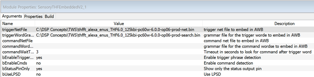
SensoryTHF_V6 Module Arguments Tab
Resource Requirement
We measured the computational load and data memory usage on RT685 HiFi4 core. The power control logic progressively activates or deactivates a part of the reference design computations. The data memory usage is determined in the design time, and is not affected by the power control logic.
This is a high-level breakdown table of the phase 3 reference design on RT685 Hifi4 core. The measurement was done with AWE-Core AC-8.C.9.
Table: Breakdown of Resource Usage
Processing Type | CPU Load (MHz) | SRAM Usage (KB) |
Own Voice Processing | 56 | 143 |
Ambient Sound Processing1 | 7 | 1 |
Playback Processing2 | 155 | 213 |
VisiSonics stereo externalization | 80 | 141 |
Mimi streaming personalization | 54 | 15 |
Sensory keyword detection | 14 | 53 |
Others3 | 0 | 100 |
Total | 232 | 510 |
Notes:
Includes only Transparency EQ and Corrective EQ
Includes VisiSonics and Mimi
I/O buffer and wire scratch memory
Use Case Analysis
Each use case requires a full system or sub-set of signal processing features in the reference design. These are possible use cases
Always ON
Own voice processing and keyword detection
Own voice processing, keyword detection and ambient sound processing
Own voice processing, keyword detection and voice command detection (not available yet)
Own voice processing, keyword detection, voice command detection and ambient sound processing (not available yet)
Always on + streaming audio listening - any combination of items below and the items in Always ON
EQ and output limiter
EQ, output limiter and streaming personalization
EQ, output limiter and stereo externalization without head tracking
EQ, output limiter, streaming personalization, and stereo externalization without head tracking
Always on + Voice Call - any combination of items below and the items in Always ON
voice call Rx without personalization
voice call Rx without personalization (not available yet)
The following are the resource requirements of each use case. Choose any combination of Always ON items (1 or 2) and others (3, 4., 5, 6 or 7) and add them together.
Table: Resource Usage of Various Use Cases
ID | Use Case | MIPS | SRAM (KB) | |
1 | Always ON | Own voice processing and keyword detection | 70 | 283 |
2 | Own voice processing, keyword detection and ambient sound processing | 80 | 286 | |
3 | Streaming Audio Listening | EQ and output limiter | 21 | 57 |
4 | EQ, output limiter and streaming personalization | 75 | 72 | |
5 | EQ, output limiter and stereo externalization without head tracking | 101 | 198 | |
6 | EQ, output limiter, streaming personalization, and stereo externalization without head tracking | 155 | 213 | |
7 | Voice Call | voice call Rx without personalization | 29 | 65 |
Finally, the table below shows the power consumption of multiple stages of automatic feature enablement on Phase 3+ system. The SRAM usage always remains the same as the full system 510 kB. CPU load is higher than sub-set of the system since dynamic deactivation of modules still has some overhead power usage.
The first four are Always ON scenario. Depends on the config setting from app, choose and add the CPU load from the remaining five items. For example, if enabling ambient sound listening and basic streaming listening, CPU load will be 14+13+21 in quiet condition with no own voice.
Table: Resource Usage with the Power Control Logic
Condition | Enabled Features | CPU Load Measured (MHz) |
Quiet condition. No own voice | QSD | 17 |
Quiet condition. Own voice detected | QSD, Sensory KWD detection | 80 |
Noisy condition. No own voice | Own voice processing(BF, SCNR, fusion, etc.) | 21 |
Noisy condition. Own voice detected | Own Voice Processing. Sensory KWD detection | 80 |
enabling ambient sound listening | EQs | +9 |
enabling basic streaming listening | EQ, output limiter | +15 |
enabling streaming listening with Mimi | EQ, output limiter, Mimi | +701 |
enabling streaming listening with VisiSonics | EQ, output limiter, VisiSonics | +901 |
enabling streaming listening with Mimi and VisiSonics | EQ, output limiter, Mimi, VisiSonics | +1451 |
Note:
Includes basic streaming process