Automatic Gain Control Example
Automatic Gain Controls or AGC are commonly found in volume leveling and microphone applications. The function of an AGC is to intelligently adjust the level of a signal and manipulate the dynamic range of a signal. This section provides several different AGC designs that are applicable in a wide range of application.
Simple AGC
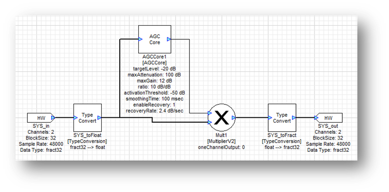
The most basic system utilizes the AGCCore module which was introduced in the Dynamics section. This modules computes the smoothed RMS level of the signal and steers the gain of the signal towards the specified targetLevel. In this example, the targetLevel is set to -20 dB and use a smoothingTime of 500 msec for slow and steady adjustment. The ratio is set to 100 indicating that the AGC will adjust the level of the signal so that the output RMS level is close to -20 dB.
Perceptual AGC
A natural step is to have the AGC take into account the perceived loudness of the signal. This is easily done by adding an equalizer in the side chain. A natural choice would be the AudioWeighting module found in the Filters folder. The ITU468 filter setting is designed to match the loudness perception of the human auditory system.
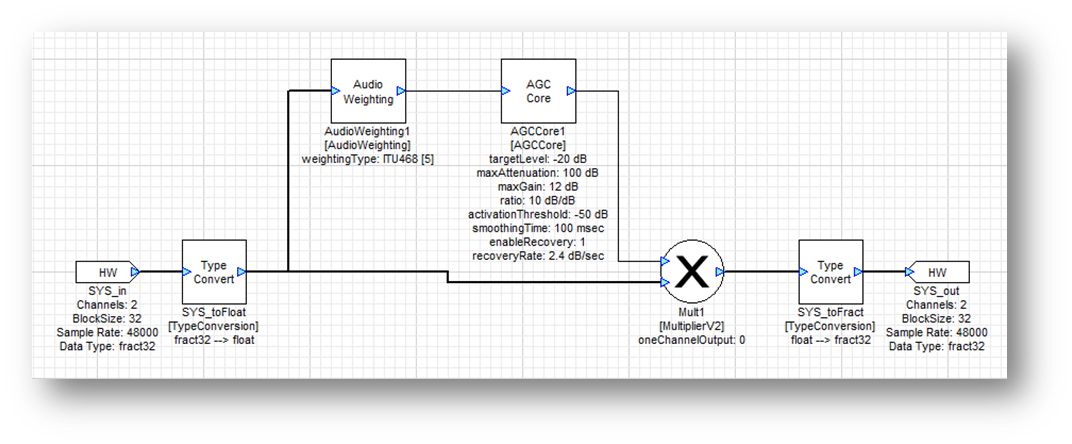
The AudioWeighting module can also do standard weightings like A-weighting, C-weighting, etc.
Two Stage AGC
The AGCCore module is designed to operate slowly on audio signals; it is analogous to turning the volume setting on the sound system. It works well over long periods of time but over shorter intervals it may let some loud peaks through. To prevent this reduce the smoothingTime of the AGCCore but this is not a good solution since artifacts will be heard.
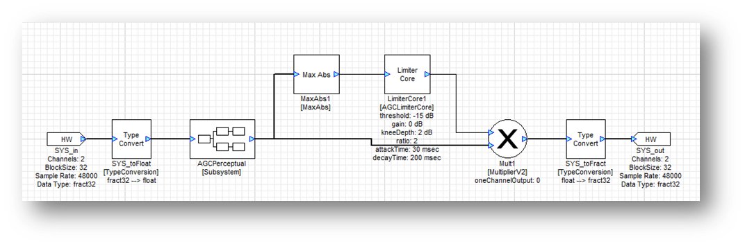
A better solution is to add a second stage of processing – a limiter – with a faster time constant. The limiter is configured to have a threshold of -15 dB and a ratio of 2. The time constants are faster with an attackTime of 30 msec and a release time of 200 msec. When there is a sudden loud peak the limiter kicks in until the AGC has had time to make gross level changes.
Three Stage AGC
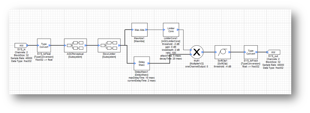
The limiter in the two stage design catches most peaks. The AGCCore module can add gain to the signal and when a loud passage follows the signal level after the AGCLimiter core may still exceed 0 dB and clip. To prevent this, add a final fast limiter stage and a soft clipper. These two modules only act on the sudden peaks and prevent clipping of the output.
Multiband AGC
All of the AGCs thus far are single band and operate on the entire signal at each stage. This can lead to pumping in which a loud low frequency signal (like a drum beat) can cause the entire signal to reduce in level. Instead, it is better to treat the low and high frequencies separately especially since there is so much energy in the low frequency. This brings us to a multiband approach in which the signal is split into two components using a crossover and treat the high and low frequencies individually.
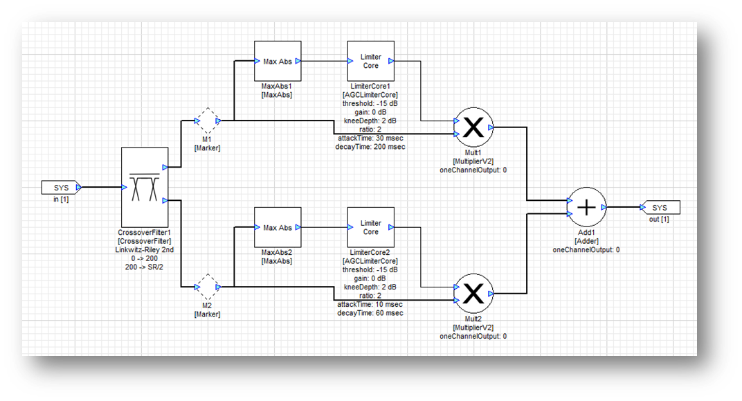
The three stage AGC above will be used as a starting point. For the multiband approach, the Limiter_Slow subsystem is capable of operating in two bands. The crossover module and two separate limiters are shown below. The crossover frequency is set to 200 Hz which does a good job separating out drum beats. The limiters are tuned so that the one operating on low frequencies has slower time constants then the one at higher frequencies.
Discrete Dynamics Processors
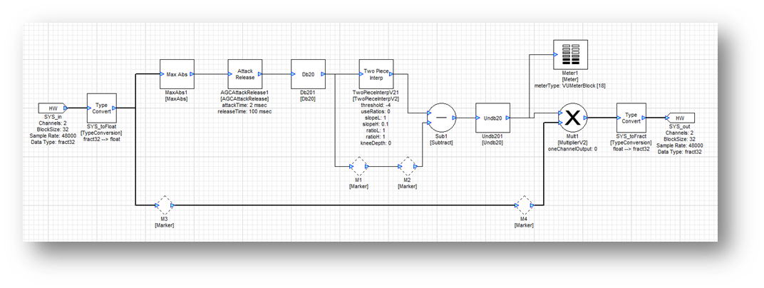
So far, dynamics processors have been built using several “core” modules: AGCLimiterCore, AGCCompressorCore, and DownwardExpanderCore. For more control, it is possible to build these “core” modules out of several discrete modules. We’ll model the AGCLimiterCore and similar approaches can be used for other modules. The block diagram is shown below:
The main steps are:
As with the limiter module, the Abs or (MaxAbs for stereo) module is used to find the maximum level of the signal in real-time. This maximum level is fed into the AGCAttackRelease module, which creates an envelope detector with specified attack and release times, in the same way that the attack and release times can be set in the limiter module.
The Db20 module converts a linear input to decibels. The gain calculation will be performed in dB units, and then the Undb20 module will be used to convert back to linear units before the computed gain is used to modify the audio.
The TwoPieceInterp module applies a piecewise function made of two lines with different slopes, connected by a smoothing polynomial (the knee). With a slope of 1 below the threshold and less than 1 above it, this will allow the system to reduce the level of the signal once it crosses the threshold, just like the limiter module.
This computed value is subtracted from the original to produce the correct gain (this may sound counterintuitive, but remember that as the level increases, a larger amount must be subtracted from the gain to produce a limiting effect).
Finally, the computed gain in dB must be converted back to linear units with the Undb20 module and fed into the AGCMultiplier module.
The modules used are:
Icon | Name | Description |
 | AGCAttackRelease | Creates envelope detector with specified attack and release times |
 | Db20 | Converts from linear units to dB |
 | TwoPieceInterp | Applies two-piece piecewise function |
 | TableInterp | Applies function from specified table interpolation |
 | Subtract | Dynamically determines a gain based on a piecewise function in order to limit a signal |
 | Undb20 | Converts from dB to linear units |
With the TwoPieceInterp module specify the slow of the gain curve above and below the threshold. One simple change can expand the functionality even further. Using a TableInterp module instead of the TwoPieceInterp allows the user to visually map out exactly the desired behavior:
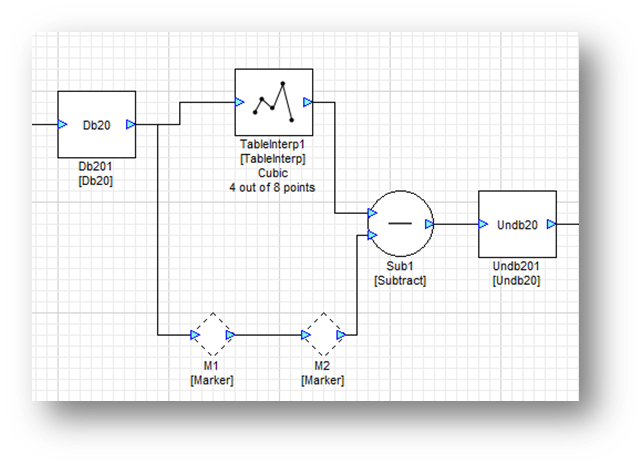
Use the TableInterp module to “draw” the input / output gain curve as shown below:
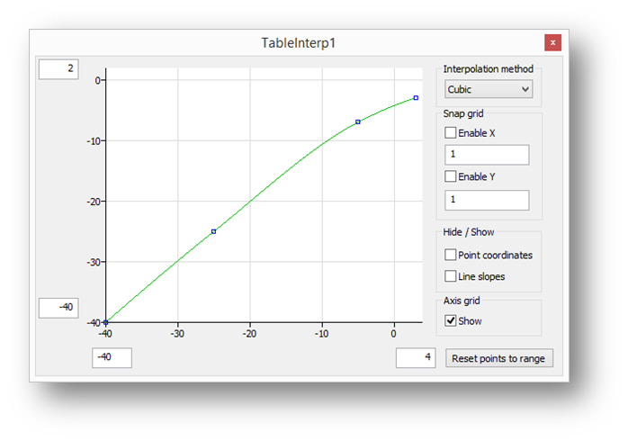
This allows for the building of highly custom dynamics processors with designed behaviors such as expansion, compression, and limiting occurring over different gain ranges.
Computationally Efficient Dynamics Processors
With the exception of the AGCCore module, the rest of the dynamics processors operate on a sample-by-sample basis and require complex mathematical calculations (dB, undB, etc.). Dynamics processors can easily consume a large amount of processing, but Audio Weaver allows for a much more efficient variation. This general technique can be used to improve the efficiency of many types of algorithms.
The main problem with the dynamics processors is that the gain calculation occurs every sample. If the time constants are on the order of several milliseconds then there is really no need to update the gains this quickly. Instead, it is possible to perform the gain calculation at a decimated rate and this is achieved using the SubblockStatistics module.
The decimation factor is specified on the module properties as the subblockSize argument:
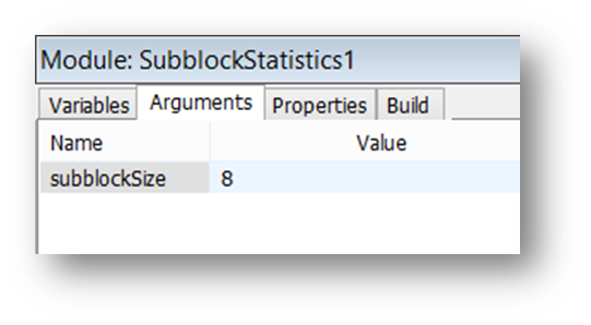
The decimation factor must be chosen so that it evenly divides the input blockSize. Next, specify on the inspector exactly which statistic is computed per subblock. The choice mirrors the ones available in the BlockStatisticsModule.
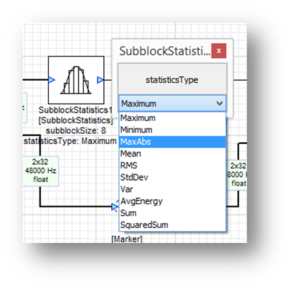
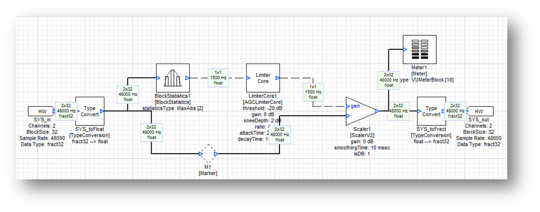
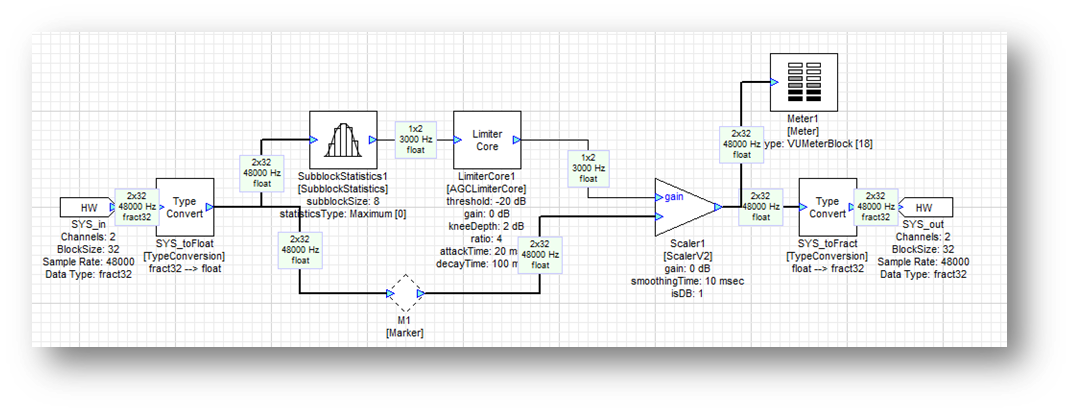
For a limiter, choose the MaxAbs statistic. Suppose that the input blockSize is 32 samples and the decimation factor is 8. The output blockSize will then be 4 samples and each sample will contain the MaxAbs value of the corresponding set of 8 input samples. A limiter built using the SubblockStatistics module is shown below. The arrangement is more efficient since the limiter is only doing 1/8 as much work as before. The Multiplier module is no longer being used. The Multiplier module requires that the blockSizes of the gain and signal pins be the same. Instead, the ScalerV2 module is used which can accept subsampled gain values.
If the signal can be decimated for the limiter even further, considering using a BlockStatistics module instead of a SubblockStatistics. This is shown below and the gain calculations are done with a blockSize of 1 sample. These signals are referred to as control signals and are described in the Logic section.