
Basic Principles of Acoustic Echo Cancellation
About This Application Note
The Basic Principles of Acoustic Echo Cancellation Application Note discusses the basic principles of acoustic echo cancellation in Audio Weaver. For additional details on acoustic echo cancellation in Audio Weaver, please refer to the Advanced Principles of Acoustic Echo Cancellation Application Note and the Help pages for the Acoustic Echo Cancellation modules.
Basic Principles of Acoustic Echo Cancellation
An audio system that includes both a microphone and a loudspeaker is vulnerable to acoustic echo, which occurs when a sound played from the loudspeaker and its acoustic reflections are captured by the microphone. Acoustic echo cancellation (AEC) algorithms analyze and process microphone input and loudspeaker output signals to reduce the presence of acoustic echo in the microphone signal(s). In Audio Weaver, AEC modules accomplish this using the following iterative procedure:
Make an initial estimate of the acoustic echo transfer function using adaptive filters in the frequency domain.
Apply the filters to a reference copy of the loudspeaker output signal(s).
Subtract the filtered reference signal(s) from the microphone input signal(s) to reduce acoustic echo in the resulting AEC output signal(s).
Adjust the filter coefficients to minimize the transfer function estimation error as indicated by the AEC output signal(s).
Repeat Steps #2-5.
Example
Figure 1 shows an example layout demonstrating basic usage of an AEC module in Audio Weaver.
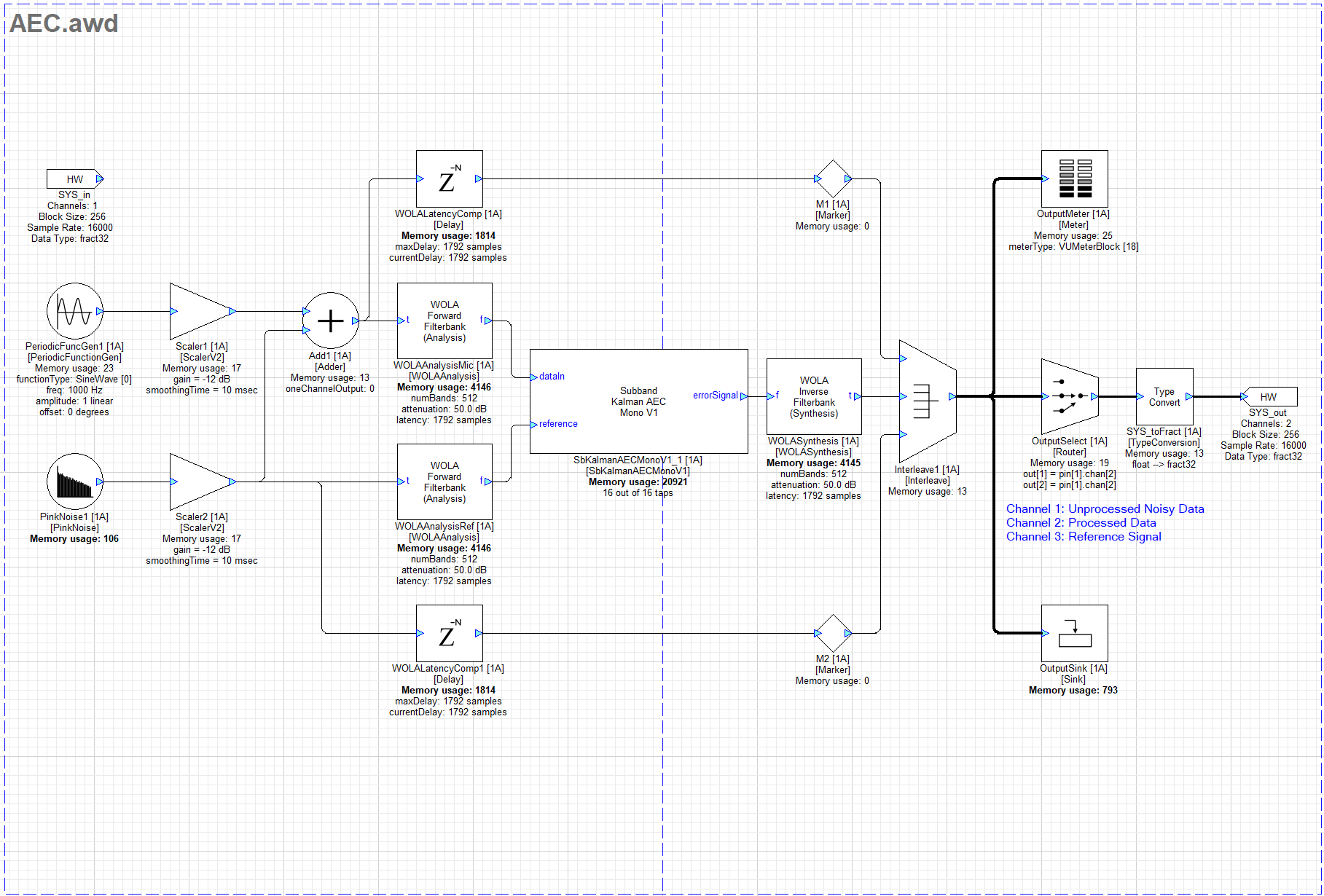
Figure 1: Example layout demonstrating basic usage of an AEC module in Audio Weaver
Note: This example uses an SbKalmanAECMonoV1 module since the reference signal in the layout is one channel. The same basic usage principles apply to all AEC modules in Audio Weaver.
This example uses a PeriodicFuncGen module generating a 1 kHz sine tone to simulate a microphone input signal and a PinkNoise module to simulate a loudspeaker output signal. Scaler modules reduce each signals’ amplitude to avoid clipping, and the pink noise is added to the 1 kHz sine tone to simulate acoustic echo. Both signals are converted to the frequency domain using WOLAAnalysis modules and are then sent to the AEC module. A WOLASynthesis module converts the AEC module’s output signal to the time domain. The processed output signal is interleaved with time-aligned copies of the simulated microphone input and loudspeaker output signals for visualization with a Meter and a Sink module.
Note: In this example, the simulated acoustic echo is identical to the reference copy of the loudspeaker output signal. These signals will not be identical in a real scenario for various reasons, including the elapsed time for the loudspeaker output signal to acoustically feed back to the microphone, the addition of acoustic reflections of the loudspeaker output signal, and the presence of nonlinearities affecting the output signal such as loudspeaker distortion. These factors decrease the accuracy of the reference signal and may consequentially degrade the AEC’s performance. The elapsed time for acoustic feedback to occur can be addressed by applying a calibrated Delay module to the reference signal in Audio Weaver before conversion to the frequency domain to time-align the reference signal with the acoustic echo in the unprocessed microphone input signal. The length of the AEC module’s adaptive filters can be adjusted to compensate for acoustic reflections in spaces with differing echo tail lengths. Nonlinearities affecting the output signal are inherently difficult to correct with signal processing and should therefore be minimized using other methods.
Arguments
Figure 2 shows the AEC module’s Arguments tab with default settings.
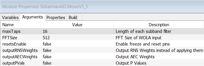
Figure 2: AEC module Arguments tab with default settings
The maxTaps argument determines the maximum length of the AEC’s adaptive filters. Each tap is the length of one block of incoming audio data, which is 16ms in the example layout.
The FFTSize argument is used for calculating an internal adaptation constant value. The FFTSize value should match the FFT size used for the WOLA modules.
Arguments for exposing optional input pins for control and output pins for returning internal variable values are disabled by default.
Variables
Figure 3 shows the AEC module’s inspector window and Variables tab with default settings.
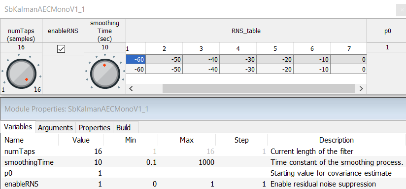
Figure 3: AEC module inspector window and Variables tab with default settings
The numTaps variable allows the length of the adaptive filters to be adjusted during run-time.
The smoothingTime variable affects the speed at which the adaptive filter coefficients adjust to improve the transfer function estimate. Values for this variable are in units of seconds.
The P0 variable initializes an internal array of values corresponding to the confidence of the estimated transfer function. A high P0 values indicate less confidence in the initial estimate and results in greater adjustment of the filter coefficients, and a low P0 values indicate more confidence and results in less adjustment. DSP Concepts recommends starting with the default P0 value of 1.
The enableRNS variable toggles optional Residual Noise Suppression processing on and off. The RNS processing supplements the adaptive filters by further reducing the AEC’s output signal level. The amount of reduction is determined by a 7-point linear interpolation table with input and output values specified in dBFS. By default, the table’s input and output values are set to pass the input signal without applying additional reduction.