
Examples Module Library
This section discusses examples which illustrate advanced module design techniques. The modules are part of the Examples module library introduced in Scaler Smoothed Module Example. In addition to the scaler_smoothed_example_module.m, this library contains the following:
scaler_example_module.m — Simple scaler. This module demonstrates how to support multiple input and output pins each with, possibly, a different number of channels.
peak_hold_example_module.m — Similar to a level meter in that it measures the peak signal level. This module demonstrates how to allocate arrays and update array sizes within the module's prebuild function. A fixed-point version of this example is also provided: peak_hold_example_fract32_module.m.
fader_example_module.m — Front-back fader which pans a signal between two different outputs. This module demonstrates compiled subsystems, that is, how to build a new module class out of a subsystem. A fixed-point version of this example is also provided: fader_example_fract32_module.m.
downsampler_example_module.m — Downsampler which keeps 1 out of every D samples; no filtering is performed. This module demonstrates how to operate on arbitrary 32-bit data types as well as changing the output block size and sample rate.
lah_limiter_example_module.m — Look ahead limiter delivered as a compiled subsystem. This module demonstrates some advanced features of compiled subsystems including initializing internal module variables and clarifying wire buffer usage.
The example library is found in the 📁 <AWE>\AWEModules\Source\Examples directory. Run the main script make_examples.m to generate code for the entire library.
Scaler Module
This example is contained in the file scaler_example_module.m. It is equivalent to scaler_module.m provided in the Deprecated module library. This module implements a straightforward linear scaler without any smoothing. The module scaler_smoothed_example_module.m implements linear scaler with smoothing. The module has single input pin and single output pin with arbitrary number of channels. This module illustrate the basic components of Audio Weaver module.
The input arguments to the MATLAB constructor function are:
function M = scaler_example_module(NAME)
It has only one argument and which is the name of the module (a string).
We next create and name the @awe_module object
M=awe_module('ScalerExample', 'Linear multichannel scaler');
if (nargin == 0)
    return;
end

M.name=NAME;
Then set the MATLAB processing function:
M.processFunc=@scaler_example_process;
Input and output pins are added to the module. The module has one input pin and one output pin with arbitrary number of channels.
PT=new_pin_type([], [], [], 'float', []);
add_pin(M, 'input', 'in', 'Input signal', PT);
add_pin(M, 'output', 'out', 'Output signal', PT);
The .gain variable is added. This gain is applied across all channels:
add_variable(M, 'gain', 'float', 1, 'parameter', 'Linear gain');
The default range information for the variable is set. This can be changed after the module has been instantiated in MATLAB and is used when drawing the inspector. We also set the units to 'linear'. This is just for display purposes and as a reminder in the documentation.
M.gain.range=[-10 10];
M.gain.units='linear';
The C file containing the processing function is specified
awe_addcodemarker(M, 'processFunction',
      'Insert:InnerScalerExample_Process.c');
followed by documentation for the module:
awe_addcodemarker(M, 'discussion', {'The Scaler module scales multichannel signals by a single gain value. ', ...
'', ...
'This module is an example to be used with the documentation.'});
We also indicate that the module can reuse the same wires for input and output.
M.wireAllocation='across';
Next code is the module browser information used by Audio Weaver Designer. It describes to Audio Weaver Designer where to place the module in the tree, the image of the module under tree, search tag and the basic shape of the module in the Designer.
M.moduleBrowser.path = 'Examples';
M.moduleBrowser.image = '../images/ExamplesIcon.bmp';
M.moduleBrowser.searchTags = 'gain volume';
M.shapeInfo.basicShape = 'triangle';
M.shapeInfo.legend = 'gain';
The processing code is contained in the file InnerScalerExample_Process.c.
M.moduleBrowser.path = 'Examples';
M.moduleBrowser.image = '../images/ExamplesIcon.bmp';
M.moduleBrowser.searchTags = 'gain volume';
M.shapeInfo.basicShape = 'triangle';
M.shapeInfo.legend = 'gain';
The processing code is contained in the file InnerScalerExample_Process.c.
awe_modScalerExampleInstance *S = (awe_modScalerExampleInstance *)pInstance;
WireInstance **pWires = ClassModule_GetWires(S);
FLOAT32 *inPtr;
FLOAT32 *outPtr;
INT32 sample, numSamples;

inPtr = (FLOAT32 *)(pWires[0]->buffer);
outPtr = (FLOAT32 *)(pWires[1]->buffer);
numSamples = (INT32) ClassWire_GetNumSamples(pWires[0]);

for(sample = 0; sample < numSamples; sample++)
{
    outPtr[sample] = inPtr[sample] * S->gain;
}
The macro
int numSamples = ClassModule_GetNumSamples(pWires[0]);
gets the total number of samples of the input pin, which same as output pin size. We then loop over for numSamples and apply the S->gain for each sample on input and store in output. The input data is located at:
pWires[0]->buffer
and the output data is placed into
pWires[1]->buffer
Peak Hold Module
The peak hold module demonstrates the use of variable size arrays and shows how the constructor function can be specified completely in MATLAB code. The peak hold module has a single multichannel input pin. The module computes the maximum absolute value for each channel on a block-by-block basis. The module records the peak absolute value seen since the module started running and also computes a peak detector with settable attack and decay rates. In many ways, the peak hold module is similar to a meter module working in block-by-block mode. This module is contained within the file peak_hold_example_module.m. A related fixed-point version is found in peak_hold_example_fract32_module.m
The module begins in the usual way. The MATLAB function takes a single argument which is the name of the module:
function M=peak_hold_module(NAME)
We then create the underlying module object, set its name and also set three internal functions.
M=awe_module('PeakHoldExample', 'Displays peak value');
if (nargin == 0)
    return;
end
M.name=NAME;
M.preBuildFunc=@peak_hold_example_prebuild;
M.setFunc=@peak_hold_example_set;
M.processFunc=@peak_hold_example_process;
Next an input pin is added. This pin accepts floating-point data and places no restrictions on the block size or sample rate.
PTIN=new_pin_type;
add_pin(M, 'input', 'in', 'audio input', PTIN);
Several top-level parameters are added. These parameters set the attack and decay times (in milliseconds) and also specify a variable which allows the peak values to be reset.
add_variable(M, 'Reset', 'int', 0, 'parameter', 'reset the current peak values');
M.Reset.range=[0 1];

add_variable(M, 'attackTime', 'float', 0.01, 'parameter', 'Envelope detector attack time constant');
M.attackTime.units='msec';
M.attackTime.range=[0 100];

add_variable(M, 'decayTime', 'float', 0.01, 'parameter', 'Envelope detector decay time constant');
M.attackTime.units='msec';
M.attackTime.range=[0 100];
Add two additional hidden variables which are the attack and decay coefficients. These coefficients are computed based on the sampling rate and block size and the calculation occurs within the set function. Both variables are marked as being hidden.
add_variable(M, 'attackCoef', 'float', 0, 'derived', 'Computed coefficient used for attack');
M.attackCoef.isHidden=1;

add_variable(M, 'decayCoef', 'float', 0, 'derived', 'Computed coefficient used for decay');
M.attackCoef.isHidden=1;
The next part is key to this example. We add two arrays whose size depends upon the number of channels in the input signal. The code is:
add_array(M, 'peakHold', 'float', [], 'state', 'Array of peak values');
M.peakHold.arrayHeap='AWE_HEAP_FAST2SLOW';
M.peakHold.arraySizeConstructor='ClassWire_GetChannelCount(pWires[0]) * sizeof(float)';

add_array(M, 'peakDecay', 'float', [], 'state', 'Array of decaying peak values');
M.peakDecay.arrayHeap='AWE_HEAP_FAST2SLOW';
M.peakDecay.arraySizeConstructor='ClassWire_GetChannelCount(pWires[0]) * sizeof(float)';
At this point, the array is set to the empty matrix; its size is based on the number of input channels which is currently not known. The array size is set below in the module's prebuild function.
Two additional fields are set for each array variable. These variables provide information enabling the C constructor function to be automatically generated. For each array, a call to the framework memory allocation function is made
void *awe_fwMalloc(size_t size, UINT heapIndex, int *retVal);
The first argument is the number of words to allocate (the size) and the second argument specifies which memory heap to allocate the memory from. In the MATLAB code, set:
M.peakHold.arraySizeConstructor='ClassWire_GetChannelCount(pWires[0]) * sizeof(float)';
This string becomes the first argument to awe_fwMalloc(). The variable pWires is an argument to the constructor function and points to an array of wire pointers. The code contained in the string determines the number of channels in the first input wire and multiplies by sizeof(float). The net result is the amount of memory to allocate for the array.
The second argument to the awe_fwMalloc function is specified by the MATLAB code
M.peakHold.arrayHeap='AWE_HEAP_FAST2SLOW';
This value is #define'd within Framework.h and specifies that memory should first be taken from the fast internal heap, and if this heap is full, is should then be taken from the slow heap.
Together, the .arraySizeConstructor and .arrayHeap settings get turned into the following code by the code generator:
if ((S->peakHold = (float *) awe_fwMalloc(ClassWire_GetChannelCount(pWires[0]) * sizeof(float), AWE_HEAP_FAST2SLOW, retVal)) == 0)
    {
        // Error code is in *retVal
        return 0;
    }
This process repeats for the second array .peakDecay.
Thus far, the code pieces within MATLAB generate the C constructor function. MATLAB also needs to know the sizes of the arrays for tuning and in order to draw the user interface. The arrays sizes are set in the MATLAB prebuild function. This is also located in the file peak_hold_example_module.m:
function M=peak_hold_example_prebuild(M)

numChannels=M.inputPin{1}.type.numChannels;

M.peakDecay.size = [numChannels 1];
M.peakDecay = zeros(numChannels, 1);

M.peakHold.size = [numChannels 1];
M.peakHold = zeros(numChannels, 1);

return
For each array, we first set the size to [numChannels 1] and then set the default value to an array of all zeros of the same size. Note that the order of operations is important. When doing array assignments, Audio Weaver checks that the assigned data is of the appropriate size. If the code were instead
M.peakDecay = zeros(numChannels, 1);
M.peakDecay.size = [numChannels 1];
Then the first assignment of zeros() would fail since the size of the array has not yet been set.
The rest of the function is fairly straightforward. We specify the C processing and set functions using code markers
awe_addcodemarker(M, 'processFunction', 'Insert:InnerPeakHoldExample_Process.c');
awe_addcodemarker(M, 'setFunction', 'Insert:InnerPeakHoldExample_Set.c');
Documentation is then added (not shown here). A line is added to the generated C file which includes the file FilterDesign.h. This file contains some of the filter design equations used by the C set function.
awe_addcodemarker(M, 'srcFileInclude', '#include "FilterDesign.h"');
There are both MATLAB and C versions of the set function. The functions translate the high-level attackTime and decayTime variables to the low-level attackCoeff and decayCoeff variables. The MATLAB code is
function M=peak_hold_example_set(M)

SR=M.inputPin{1}.type.sampleRate;

M.attackCoef=design_smoother(M.attackTime, SR, 1);
M.decayCoef=design_smoother(M.decayTime, SR, 1);
The C code contained in InnerPeakHoldExample_Set.c is:
awe_modPeakHoldExampleInstance *S;
WireInstance **pWires;
float SR;
S = (awe_modPeakHoldExampleInstance *)pInstance;
pWires = ClassModule_GetWires(S);
SR = (float) ClassWire_GetSampleRate(pWires[0]);

S->attackCoef = design_smoother(S->attackTime, SR, 1);
S->decayCoef= design_smoother(S->decayTime, SR, 1);

return(0);
Why are two versions of the set function required? For this module, the MATLAB function is not required. After a module is allocated on the target in C, the C set function is automatically called and the coefficients computed. The MATLAB code is for convenience and can also be used for regression testing.
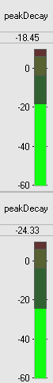
The next portion of the peak_hold_example_module.m file contains the inspector information. We only show the .peakHold variable since the others are similar or have already been discussed. The inspector drawn is:
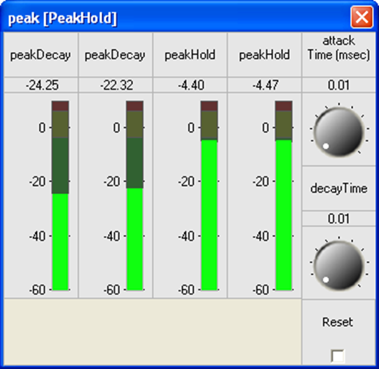
This example has a stereo input. The first two meters shown are .peakDecay for both channels. The second two meters show .peakHold. The MATLAB code for drawing the .peakDecay meters is:
M.peakDecay.guiInfo.transposeArray=1;
M.peakDecay.guiInfo.range=[-60 10];
M.peakDecay.guiInfo.controlType='meter';
M.peakDecay.guiInfo.attribStr='mapping=db20';
add_control(M, '.peakDecay', 'topRight');
The .peakDecay variable is defined in MATLAB as a column vector. In this case, since there are two input channels, the vector is of dimension 2x1. When the meter control is drawn, the default behavior is to draw it as 2 high and 1 wide (this matches the MATLAB variable size)
This is not what we want — we want the controls to be side by side. To achieve this, the array of values has to be transposed to form a row vector. The statement
M.peakDecay.guiInfo.transposeArray=1;
achieves this. Next, the range of the control is set, the variable is tied to a meter control, and finally, the control is instructed to convert from linear measurements to dB for display. This completes the MATLAB code for the .peakDecay inspector control. The .peakHold inspector specification is almost identical.
The last portion of the file is module browser information as explained in scaler module example above.
M.moduleBrowser.path = 'Examples';
M.moduleBrowser.image = '../images/ExamplesIcon.bmp';
M.moduleBrowser.searchTags = 'peak hold';
M.shapeInfo.legend = 'Peak Hold';
M.shapeInfo.size = [6 6];
The C processing function is straightforward and is not shown here. Refer to the file InnerPeakHoldExample_Process.c.
Fader module
This example teaches how to create a new module class out of a subsystem and shows how to implement a custom bypass function. The fader module has a single mono input pin, a stereo output pin, and 3 internal modules:
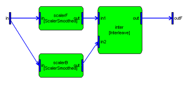
The input signal is scaled by scalerF to yield the front channel and by scalerB to yield the back channel. The output pin is stereo with the first channel representing the front and the second channel the back. The scalers are set so that a portion of the input signal is fed to each of the front and back channels. The fader implements constant energy panning using a sine/cosine response.
The fader example is found in fader_example_module.m. As usual, create a subsystem and set its .name based on an argument to the function.
SYS=awe_subsystem('FaderExample', 'Splits a mono input signal into front and back channels with constant energy panning.');
if (nargin == 0)
    return;
end
SYS.name=NAME;
Add input and output pins. The input pin is a single channel without any restrictions on the blockSize or sampleRate. The output pin is stereo without any restrictions on the blockSize or sampleRate.
PTIN=new_pin_type(1);
PTOUT=new_pin_type(2);

add_pin(SYS, 'input', 'in', 'audio input', PTIN);
add_pin(SYS, 'output', 'out', 'audio output', PTOUT);
Then add the modules to create the subsystem
add_module(SYS, scaler_smoothed_module('scalerF'));
add_module(SYS, scaler_smoothed_module('scalerB'));
add_module(SYS, interleave_module('inter', 2));
Then connect them together:
connect(SYS, '', 'scalerF');
connect(SYS, 'scalerF', 'inter.in1');
connect(SYS, '', 'scalerB');
connect(SYS, 'scalerB', 'inter.in2');
connect(SYS, 'inter', '');
None of the bypass functions provided with Audio Weaver is suitable for this module. The desired bypass behavior is to copy the input channel to each of the two output channels and scale by 0.707. To implement this custom bypass functionality, write an inner bypass function as shown below:
awe_modFaderExampleInstance *S = (awe_modFaderExampleInstance *)pInstance;
WireInstance **pWires = ClassModule_GetWires(S);
FLOAT32 *in = (FLOAT32 *) pWires[0]->buffer;
FLOAT32 *outF = (FLOAT32 *) pWires[1]->buffer;
FLOAT32 *outB = (FLOAT32 *) outF + 1;
UINT32 numSamples = ClassWire_GetNumSamples(pWires[0]);
INT32 sample;
/*awe_vecScale((FLOAT32 *)(pWires[0]->buffer), 1,
                (FLOAT32 *)(pWires[1]->buffer), 2,
                (float)0.707, numSamples);*/

for(sample = 0; sample < (INT32)numSamples; sample++)
{
    *outF = in[sample] * 0.707f;

    outF += 2;
}

/*awe_vecScale((FLOAT32 *)(pWires[0]->buffer), 1,
                (FLOAT32 *)(outB), 2,
                (float)0.707, numSamples);*/

for(sample = 0; sample < (INT32)numSamples; sample++)
{
    *outB = in[sample] * 0.707f;

    outB += 2;
}
Then set the 'bypassFunction' code marker to insert this file:
awe_addcodemarker(SYS, 'bypassFunction', 'Insert:code\InnerFaderExample_Bypass.c');
The key lesson this example is the MATLAB code
SYS.flattenOnBuild=0;
This identifies the subsystem as one that is not flattened when building. That is, the FaderExample module class exists natively on the target. The Server only sends a single command to the target and the entire subsystem will be instantiated. The automatically generated constructor function is found in ModFaderExample.c and shown below. The constructor function allocates the base module and then allocates each of the 3 internal modules. The module is marked as requiring a total of 4 pins: 1 input, 1 output, and 2 scratch. These pins are allocated outside of the function and then passed in. By looking through the code you can see how the wire information is passed to each of the internal modules' constructor function.
AWE_MOD_SLOW_CODE
ModInstanceDescriptor *awe_modFaderExampleConstructor(int * FW_RESTRICT retVal, UINT nIO, WireInstance ** FW_RESTRICT pWires, size_t argCount, const Sample * FW_RESTRICT args)
  {
    // Create the module which holds the overall subsystem
    awe_modFaderExampleInstance *S = (awe_modFaderExampleInstance *) BaseClassModule_Constructor(&awe_modFaderExampleClass, retVal,
										   ClassModule_PackFlags(1, 1, 2),
										   pWires, argCount, args);

    {
      WireInstance *scalerFWires[2]={ pWires[0], pWires[2] };
      Sample scalerFArgs[4];
      scalerFArgs[0].fVal = 7.0710677e-001f; // scalerF.gain
      scalerFArgs[1].fVal = 1.0000000e+001f; // scalerF.smoothingTime
      scalerFArgs[2].fVal = 7.0710677e-001f; // scalerF.currentGain
      scalerFArgs[3].fVal = 2.0811646e-003f; // scalerF.smoothingCoeff
      S->scalerF = (awe_modScalerSmoothedInstance *) ClassModule_Constructor(CLASSID_SCALERSMOOTHED, retVal, ClassModule_PackFlags(1, 1, 0), scalerFWires, 4, (Sample *)scalerFArgs);
      if (S->scalerF == NULL)
	{
	  // Error code is in *retVal
	  return 0;
	}
    }
    {
      WireInstance *scalerBWires[2]={ pWires[0], pWires[3] };
      Sample scalerBArgs[4];
      scalerBArgs[0].fVal = 7.0710677e-001f; // scalerB.gain
      scalerBArgs[1].fVal = 1.0000000e+001f; // scalerB.smoothingTime
      scalerBArgs[2].fVal = 7.0710677e-001f; // scalerB.currentGain
      scalerBArgs[3].fVal = 2.0811646e-003f; // scalerB.smoothingCoeff
      S->scalerB = (awe_modScalerSmoothedInstance *) ClassModule_Constructor(CLASSID_SCALERSMOOTHED, retVal, ClassModule_PackFlags(1, 1, 0), scalerBWires, 4, (Sample *)scalerBArgs);
      if (S->scalerB == NULL)
	{
	  // Error code is in *retVal
	  return 0;
	}
    }
    {
      WireInstance *interWires[3]={ pWires[2], pWires[3], pWires[1] };
      S->inter = (awe_modInterleaveInstance *) ClassModule_Constructor(CLASSID_INTERLEAVE, retVal, ClassModule_PackFlags(2, 1, 0), interWires, 0, (Sample *)NULL);
      if (S->inter == NULL)
	{
	  // Error code is in *retVal
	  return 0;
	}
    }

    return ((ModInstanceDescriptor *) S);
}
Similarly, since this module is created out of a subsystem, there is no need to provide a processing function; it will be automatically generated by Audio Weaver. (Yes, a custom processing function could be supplied, but the generated one works fine.) The automatically generated processing function is shown in ModFaderExample.c. It simply calls the 3 processing functions for the 3 internal modules:
AWE_MOD_FAST_CODE
void awe_modFaderExampleProcess(void *pInstance)
{
  awe_modFaderExampleInstance *S = (awe_modFaderExampleInstance *) pInstance;

  ClassModule_Execute(S->scalerF);
  ClassModule_Execute(S->scalerB);
  ClassModule_Execute(S->inter);
}
The set function for the subsystem takes the high-level .smoothingTime variable and passes it down to each of the internal smoothed scaler modules. The function also takes the .fade variable and computes two separate gains using a sin/cos pan.
{
  awe_modFaderInstance *S;
  float arg;

  S = (awe_modFaderInstance *)pInstance;

  S->scalerF->smoothingTime=S->smoothingTime;
  S->scalerB->smoothingTime=S->smoothingTime;

  // Compute the front and back gains from the .fade setting.
  arg = (float)((1+S->fade)*PIDIV4);
  S->scalerF->gain = sinf(arg);
  S->scalerB->gain = cosf(arg);

  ClassModule_Set(S->scalerF, MASK_ScalerSmoothed_smoothingTime | MASK_ScalerSmoothed_gain);
  ClassModule_Set(S->scalerB, MASK_ScalerSmoothed_smoothingTime | MASK_ScalerSmoothed_gain);

  return(0);
}
The function sets the high-level variables of the smoothed scaler modules and then calls the set function for the module. The set function takes a pointer to the smoothed scaler module and also a bit mask which identifies the specific variables that were modified. In this case, we are setting the smoothingTime and gain fields of the modules.
The last portion of the file is module browser information as explained in scaler module example above.
SYS.moduleBrowser.path = 'Examples';
SYS.moduleBrowser.image = '../images/E.bmp';
SYS.moduleBrowser.searchTags = 'fader';
SYS.shapeInfo.legend = 'Fader';
SYS.shapeInfo.size = [10 6];
There is also a fract32 version of this module called fader_example_fract32_module.m See this module for examples of fixed-point processing.
Downsampler Module
This module downsamples a signal by keeping only one out of every D input samples. This example demonstrates two further techniques used when creating audio modules. First, the module essentially copies 32-bit samples from input to output and doesn't care if the data type is float, fract32, or int. All of these types will work with the same processing function. This is obvious in C but this flexibility must be encoded into the MATLAB scripts. The second technique shown is how to change the block size and sample rate as part of the prebuild function.
This example is contained in the file downsampler_example_module.m and is equivalent to downsampler_module.m found in the Advanced module library.
The MATLAB code defining the input and output pins of the module is:
PT=new_pin_type([], [], [], '*32');
add_pin(M, 'input', 'in', 'Input signal', PT);
add_pin(M, 'output', 'out', 'Output signal', PT);
In this case, the data type is specified as '*32'. This abbreviation is expanded to all possible 32-bit data types in the add_pin function: {'float', 'fract32', 'int'}. It is possible to specify the data type to the new_pin_type call as the cell array
{'float', 'fract32', 'int'}
Using the '*32' abbreviation gives us flexibility in case the set of data types is ever expanded in the future.
The decimation factor D is the second argument to the MATLAB function and is specified at instantiation time. The variable D appears in the instance data structure and its usage is listed as 'const'. This means that the variable D can no longer be changed.
add_variable(M, 'D', 'int', D, 'const', ...
'Decimation factor.  1 out of every D samples is output');
The module's prebuild function computes the type of the output pin. The block size and sample rate are reduced by the decimation factor D; the number of channels and data type are unchanged. We also verify that the block size of the input is divisible by the decimation factor:
blockSize=M.inputPin{1}.type.blockSize;

if (rem(blockSize, M.D) ~= 0)
	warning('The downsample factor D does not evenly divide the blockSize');
	newBlockSize=floor(blockSize/M.D);
else
	newBlockSize=blockSize/M.D;
end

M.outputPin{1}.type.sampleRate=M.inputPin{1}.type.sampleRate/M.D;
M.outputPin{1}.type.numChannels=M.inputPin{1}.type.numChannels;
M.outputPin{1}.type.dataType=M.inputPin{1}.type.dataType;
M.outputPin{1}.type.blockSize=newBlockSize;
The module's MATLAB implementation of the processing function is found in downsampler_example_process.m. It simply returns 1 out of every D input samples.
function [M, WIRE_OUT]=downsampler_process(M, WIRE_IN)

IN=WIRE_IN{1};
WIRE_OUT{1}=IN(1:M.D:end, :);

return;
The C processing function is similar. Although written for 32-bit floats, the function works equally well with any 32-bit data type.
AWE_MOD_FAST_CODE
void awe_modDownsamplerExampleProcess(void *pInstance)
{
    awe_modDownsamplerExampleInstance *S = (awe_modDownsamplerExampleInstance *)pInstance;
    WireInstance **pWires = ClassModule_GetWires(S);
    UINT32 blockSize = ClassWire_GetBlockSize(pWires[0]);
    UINT32 numChannels = ClassWire_GetChannelCount(pWires[0]);
    UINT32 channel;
    INT32 blockSizeD = (blockSize / S->D);
    INT32 sample;

    // blockSize is the number of samples in each input channel
    // blockSizeD is the number of samples in each output channel

    FLOAT32 *src = (FLOAT32 *)pWires[0]->buffer;
    FLOAT32 *dst = (FLOAT32 *)pWires[1]->buffer;
    FLOAT32 *srcPtr, *dstPtr;

    for(channel = 0; channel < numChannels; channel++)
    {
        //awe_vecCopy(src+channel, (numChannels*S->D), dst+channel, numChannels, blockSizeD);

        srcPtr = src + channel;
        dstPtr = dst + channel;

        for(sample = 0; sample < blockSizeD; sample++)
        {
            *dstPtr = *srcPtr;

            srcPtr += numChannels*S->D;
            dstPtr += numChannels;
        }
    }
}
The last portion of the file is module browser information as explained in scaler module example above.
M.moduleBrowser.path = 'Examples';
M.moduleBrowser.image = '../images/E.bmp';
M.moduleBrowser.searchTags = 'decimation';
M.shapeInfo.svgImage = '../../images/DownSampler.svg';
M.shapeInfo.size = [6 6];
Note: The shape information is provided as custom svg image. The default shape of the module is rectangle and it can be overwrite with svgImage tag.
Look Ahead Limiter Module
This example demonstrates some advanced code generation techniques. The look ahead limiter is a dynamics processor which applies a time-varying gain to a signal. The module m-file takes two arguments.
SYS=lah_limiter_example_module(NAME, MAXDELAY)
The first is the NAME of the subsystem and the second, MAXDELAY, is the maximum amount of delay, in milliseconds. MAXDELAY is used internally when allocating the delaymsec_module.m:
add_module(SYS, delaymsec_module('delay', MAXDELAY));
SYS.delay.currentDelayTime=MAXDELAY;
The compiled subsystem contains 4 internal modules:
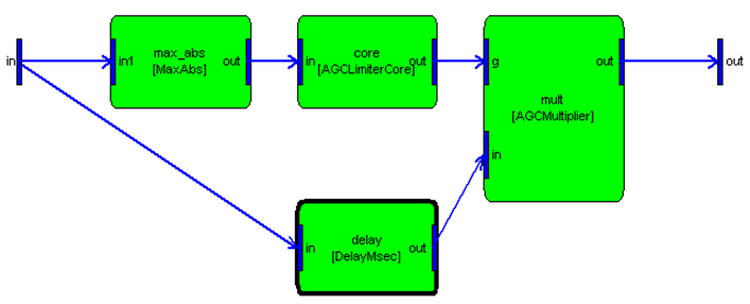
Specifying Internal Module Constructor Arguments
If we follow the normal code generation procedure, then the constructor function for the internal delaymsec_module will be:
{
  WireInstance *delayWires[2]={ pWires[0], pWires[5] };
  Sample delayArgs[2];
  delayArgs[0].fVal = 5.0000000e+000f; // delay.maxDelayTime
  delayArgs[1].fVal = 5.0000000e+000f; // delay.currentDelayTime
  S->delay = (awe_modDelayMsecInstance *) ClassModule_Constructor(CLASSID_DELAYMSEC, retVal, ClassModule_PackFlags(1, 1, 0), delayWires, 2, (Sample *)delayArgs);
  if (S->delay == NULL)
	{
	  // Error code is in *retVal
	  return 0;
	}
}
If you look at the values of the delayArgs array, you'll see that the maximum delay time of the internal module is hard coded to 5 msec. This is not what we wanted; the delay time should instead be specified at construction time.
To fix this, add a high-level variable to the look ahead limiter system. We'll name it 'maxDelayTime' to be consistent with the delaymsec_module.m.
add_variable(SYS, 'maxDelayTime', 'float', MAXDELAY, 'const', ...
'Maximum delay time');
SYS.maxDelayTime.units='msec';
Next, we'll use the maxDelayTime field of the look ahead limiter instance structure as an initializer for the maxDelayTime and currentDelayTime fields of the internal module. This is done by setting the .constructorCode field of the delaymsec_module variables as shown below:
SYS.delay.maxDelayTime.constructorCode='S->maxDelayTime';
SYS.delay.currentDelayTime.constructorCode='S->maxDelayTime';
In the automatically generated constructor code, S always refers to the base module structure which has already been allocated and initialized by BaseClassModule_Constructor(). The new constructor code for the delay is:
{
  WireInstance *delayWires[2]={ pWires[0], pWires[5] };
  Sample delayArgs[2];
  delayArgs[0].fVal = S->maxDelayTime; // delay.maxDelayTime
  delayArgs[1].fVal = S->maxDelayTime; // delay.currentDelayTime
  S->delay = (awe_modDelayMsecInstance *) ClassModule_Constructor(CLASSID_DELAYMSEC, retVal, ClassModule_PackFlags(1, 1, 0), delayWires, 2, (Sample *)delayArgs);
  if (S->delay == NULL)
	{
	  // Error code is in *retVal
	  return 0;
	}
}
The argument S->maxDelayTime initializes the internal module achieving the desired effect.
Disambiguating Wire Allocation
If look at the default subsystem including wiring information, we see:
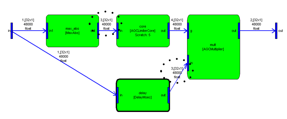
By default, the input and output pins are mono and the system ends up using 3 scratch wires:
>> SYS=lah_limiter_example_module('LAH');
>> SYS=prebuild(SYS);
>> SYS.scratchPin

ans =

    [1x1 struct]    [1x1 struct]    [1x1 struct]
This subsystem is designed to operate on an arbitrary number of channels. However, the wire allocation shown above is only applicable when the input is mono. (To see this, consider the MaxAbs module. This module always has a mono output and is assigned to wire #3. The signal path through DelayMsec can be N-channel and is also assigned to wire #3). If this system is run with stereo inputs, then the wire allocation is incorrect and the audio processing will fail.
To fix this problem, force the system input pin to have 2 channels by default.
pinType=SYS.max_abs.inputPin{1}.type;
add_pin(SYS, 'input', 'in', 'Audio Input', pinType);
SYS.inputPin{1}.type.numChannels=2;
The pin still holds an arbitrary number of channels, but its default value is 2. When the subsystem is now routed, the wires will be allocated as:
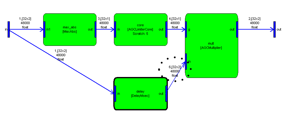
The system now requires a total of 4 scratch wires, with a new scratch wire, #6 assigned to the output of DelayMsec. Furthermore, the buffer allocation is now general purpose and will work with any number of input channels.
The last portion of the file is module browser information as explained in scaler module example above.
SYS.moduleBrowser.path = 'Examples';
SYS.moduleBrowser.image = '../images/E.bmp';
SYS.moduleBrowser.name = 'Look Ahead Limiter';
SYS.moduleBrowser.searchTags = 'lah Limiter';
SYS.shapeInfo.legend = 'Look Ahead Limiter';
SYS.shapeInfo.size = [10 6];