
Logic Binary Op Combination
About This Guide
This Application Note explains the use of the LogicBinaryOpCombination module in the Audio Weaver Application.
The LogicBinaryOpCombination Module
The LogicBinaryOpCombination module allows construction of logic equations of a specific form. While there can be multiple inputs and outputs, the following constraints apply.
For each output channel
The first operation in the sequence must be CONST in order to read the value of the first channel.
Subsequent operations must take the output of the prior operation as well as an input channel.
The output of every combination except for the last one in the sequence must only go to one input of the following operation. The output signal from the last one in the sequence is an output channel of this module.
The LogicBinaryOpCombination module can be found in Sound Design/Control folder or by using the search window in the module browser.
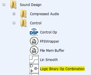
Figure 1. Location in Module Browser
The module has one input pin and one output pin. Multiple signals coming in must be interleaved onto multiple channels of a single wire. The input signals must be integers but they do not have to be boolean. The logic operations are applied bit by bit to the 32-bit integer value.
Valid and invalid combinations
The following combinations are valid:
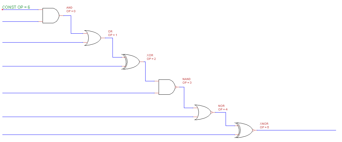
Figure 2. Single chain of cascaded gates
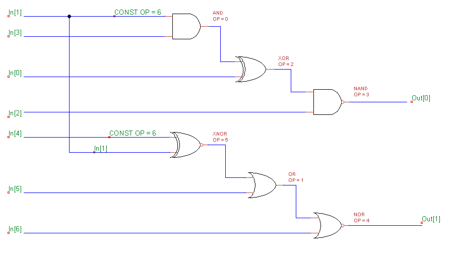
Figure 3. More than one chain, each chain with its own output.
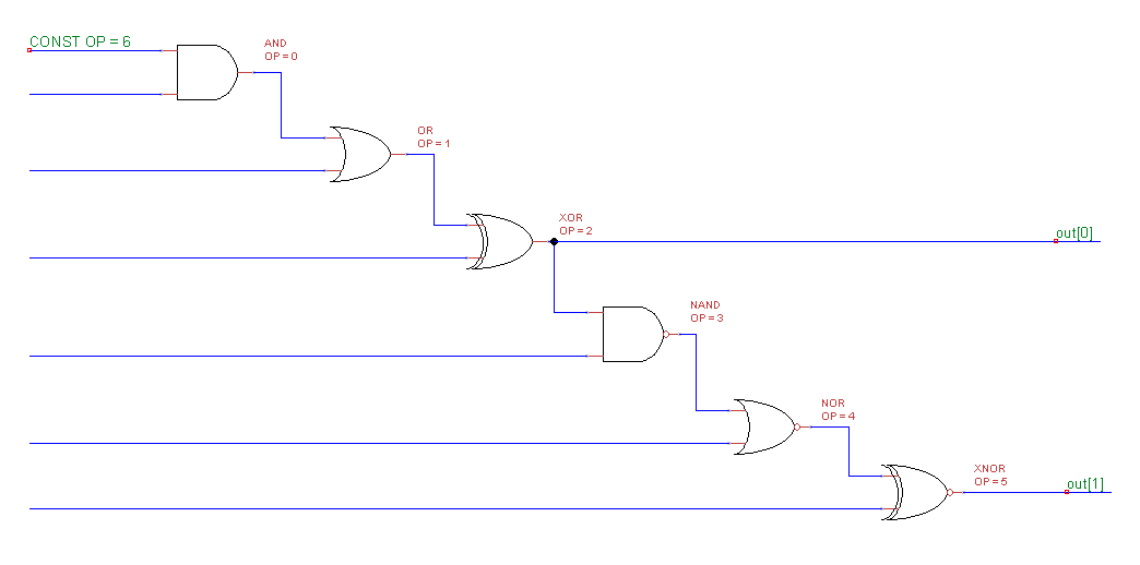
Figure 4. Multiple Outputs from a single chain
The following structures are invalid and cannot be implemented with the LogicBinaryOpCombination module. The LogicBinaryOp module should be used instead to build up these structures. You can combine the LogicBinaryOpCombination module with other logic modules as well.
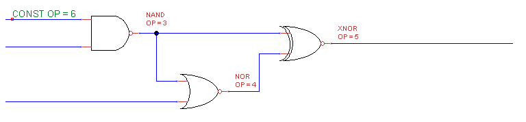
Figure 5. Error: One input of each gate must go to the module's input
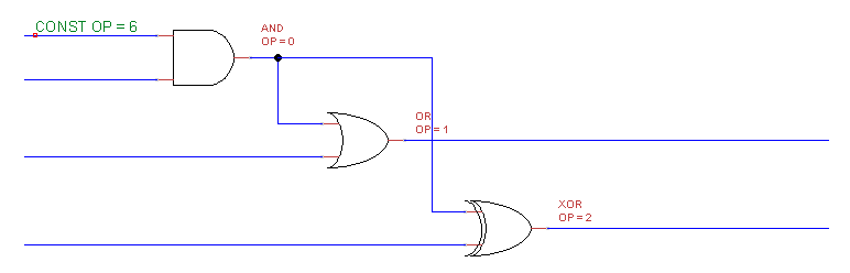
Figure 6. Error: Gate input is not from previous stage
Configuring the module as a single gate
The simplest function, which is a single logic gate, requires two operations. By default, there is only one operation defined, so you must add another one. Let’s configure a NAND gate. This section of the layout has a wire with 7 channels of int data. We want to pick off channels 2 and 5 and NAND them together.
When you first drop the module into your design, you will see this (turn on View->Module Variables).
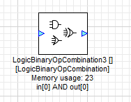
Figure 7. Layout symbol
Open the Properties panel and select the Arguments tab. Set the number of binary operations to 2.
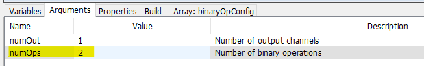
Figure 8. Set numOps
Now click on the Array:binaryOpConfig tab. Set the entries as shown, then click “Apply”.
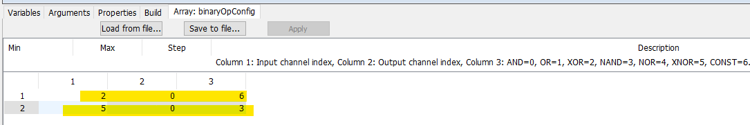
Figure 9. Edit array to set the desired function.
Confirm that the updated Module Variables are shown:
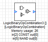
Figure 10. Confirm settings
Please note that the first logic operation requires two operations.
A CONST operation to read the value of the selected channel
The actual logic operation you wish to perform with the next channel in the table
Subsequent logic statements for this output pin only add one row each in the binaryOpConfig array. However, to start a new output pin, you must again use the CONST operation.
Here’s a module with 4 inputs and 1 output.
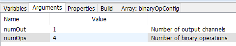
Figure 11. numOps setting for multiple inputs
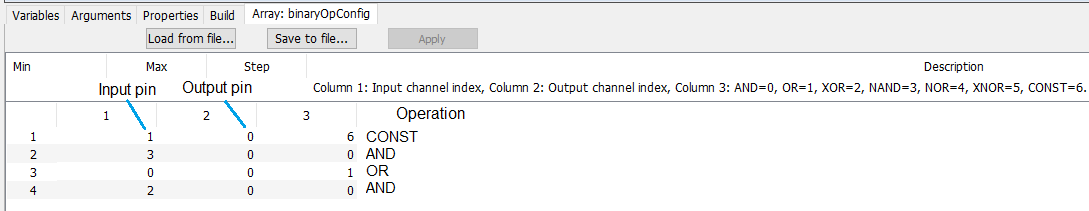
Figure 12. Array settings for multiple inputs
This implements the logic function:
Out[0] = (( In[1] & In[3] ) | In[0] ) & In[2]
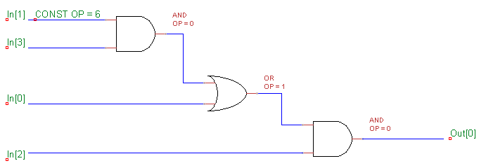
Figure 13. (( In[1] & In[3] ) | In[0] ) & In[2]
Multiple Expressions
Two expressions of three operations each are implemented below. Note that it is possible to use the same input channel in both expressions. You can add more expressions by increasing numOut. Each expression uses a single output channel.
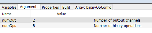
Figure 14. Arguments settings for multiple outputs
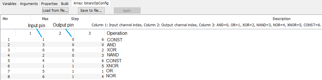
Figure 15. Array settings for multiple inputs
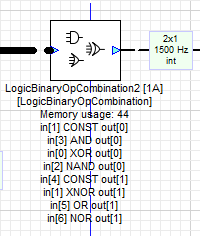
Figure 16. Confirm settings
This implements the logic functions:
Out[0] = (( In[1] AND In[3] ) XOR In[0] ) NAND In[2]
Out[1] = (( In[4] XNOR In[1] ) OR In[5] ) NOR In[6]
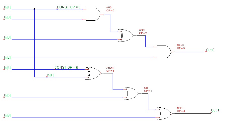
Figure 17. Equivalent logic diagram
Typical uses
Although this module cannot be used to implement arbitrary combinatorial logic with N inputs and M outputs, it can be leveraged to quickly implement wide AND and OR gates.
7-input AND gate

Figure 18. Array settings for7-AND
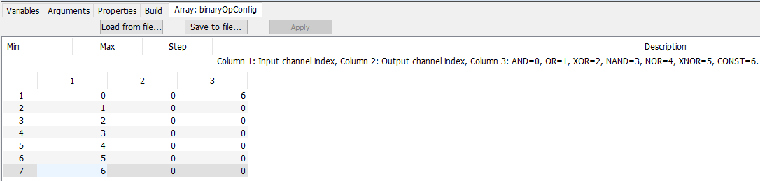
Figure 19. Argument settings for 7-AND
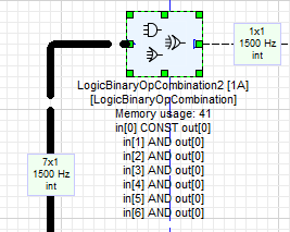
Figure 20. Confirm settings
7-input OR gate
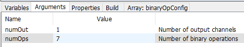
Figure 21. Array settings for 7-OR
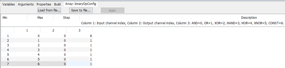
Figure 22.. Argument settings for 7-OR
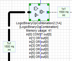
Figure 23.Confirm settings
6-input OR gate + AND
You can add an AND term onto the end to act as a global qualifier, such as a master enable for a variety of alarm sources (OR).
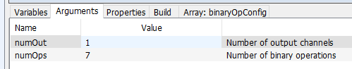
Figure 24. Argument settings for 6-OR+AND
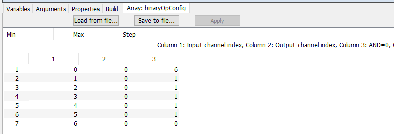
Figure 25. Array settings for 6-OR+AND
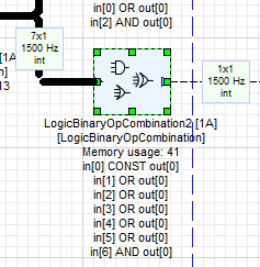
Figure 26. Confirm settings
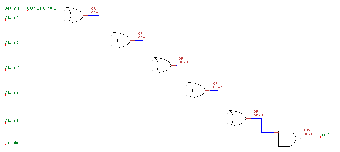
Figure 27. Equivalent logic diagram