
Random Sequencer
About This Guide
This Application Note explains the use of the Rand Sequencer module in the Audio Weaver Application.
The Rand Sequencer Module
The Rand Sequencer module can be found in the Sound Design/Control folder or by using the search window in the module browser. It is called “Rand Sequencer”.
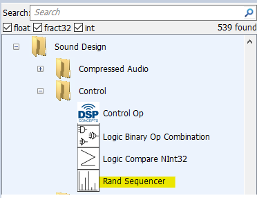
Figure 1. Location in Module Browser
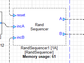
Figure 2. Layout view
How it works
Upon reset, a vector of random integers is generated and divided into two halves. Individual increment inputs step through each half independently and the selected values are output on pins A and B.
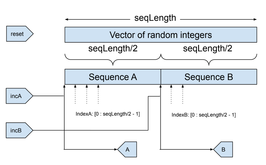
Figure 3. Block diagram
The random vector is regenerated when:
Layout starts running with reset pin high
Reset pin goes high
IndexA or IndexB is incremented from (seqLength/2 - 1)
The vector contains seqLength random integers between the value of 0 and (seqLength - 1).
Note: Depending on the CPU, there may be duplicate values in the vector.
Internal variables IndexA and IndexB are incremented by the incA and incB inputs, respectively. The individual indices are used to read the entry from the corresponding sequence and present it at the corresponding output. When either index is incremented from (seqLength/2 - 1), IndexA and IndexB are both reset to 0 and the random vector is regenerated.
incA and incB
The incX inputs expect an integer source. The index is incremented every time the corresponding incX pin’s value increases by 1. To increment the index once per cycle, use an input signal that varies between 0 and 1. The index will increment on the 0 to 1 transition. You can also use an integer counter such as the Counter module, which will insert a pause (index not incremented) when the counter wraps around to zero.
Module arguments
seqLength | Length of the randomized sequence |
Module variables
reset | Resets the random sequence on a 0 – 1 transition. |
Sample Layout – Dual Random Wave File Sequencer
If you simply wish to generate random numbers or noise, the following modules are typically adequate.
Module Name | Summary |
Rand | Random number generator, generates 32-bit integers (which can be interpreted as int or fract32). |
Randi | Generates slowly varying random noise (float) by linearly interpolating between random values. The underlying random noise lies in the range [-1 +1). The module computes a new random value at an adjustable rate. |
RandiFract32 | Similar to Randi except output is fract32 format. |
White Noise | Uniformly distributed white noise, float format, adjustable output range. |
White Noise Fract32 | Similar to White Noise except output is fract32 format. |
The Rand Sequencer module is unique in the following ways:
There are two outputs.
The sequencer calculates a vector of random numbers which is divided in half (by the index).
Each output indexes through its half of the randomized vector when it receives a rising edge on the corresponding “incX” input.
The supplied layout shows how this can be used to sequence a set of WAV files such that each file is played back once, in a random order, before the sequence is randomized again. This layout uses two WavePlayerOneShotFlash modules. These modules support changing the loaded WAV file at run time. For a more detailed explanation on how to do this, please refer to the Application Note for the WavePlayerOneShotFlash module.
Included in the ZIP file below are 10 WAV files. These need to be extracted and placed in the folder where the AWE Server binary resides, for example: C:\DSP Concepts\AWE Designer 8.D.2.2 Standard\Bin\win32-vc142-rel.
Overall Design
The sample layout includes two One Shot Wave Players, trigger generation logic, and the Rand Sequencer. The included set of wave files are the words “one”, “two”, “three” and so on, so what you will hear from the left and right channels corresponds to the values of outputs A and B respectively.
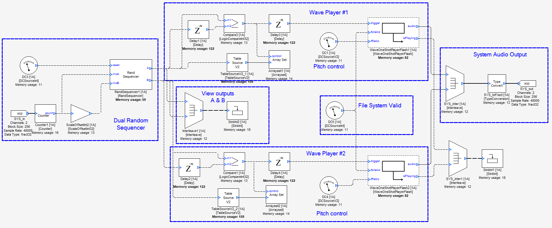
Figure 4. Sample layout
Let’s look at this one section at a time.
Dual Random Sequencer
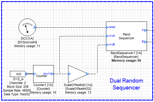
Figure 5. Dual Random Sequencer and Clock
Attaching the DC3 module to the Rand Sequencer’s reset pin automatically resets the module, generating a new random output vector, when the layout starts running. Set DC3’s value to 1.
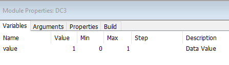
Figure 6. DC3 Properties
Module Counter1 delivers a constant rate square wave signal to incA. The period should be chosen to be longer than the longest WAV file that you intend to play.
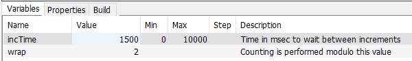
Figure 7. Counter1 properties
ScaleOffset2 inverts the signal so that incA and incB are being clocked on alternate edges of the square wave.
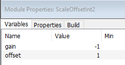
Figure 8. ScaleOffsetInt2 Properties
Count A and count B in the graph below are the internal counter state of the Rand Sequencer, not its outputs. Since incB is high at initialization time, count B immediately increments to 1.
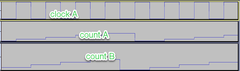
Figure 9. Clock and internal counters
This graph lines up the random outputs against the clock and internal counter states. Note several things:
When the layout starts, the output state for both outputs A and B cannot be determined. Because it’s a random number generator, the output pattern can’t be predicted either. This document shows one possible example.
Count B starts at one.
If either counter increments from (seqLength/2), the entire random sequence resets and both outputs (can) change. Count B is ahead of count A in this design and so resets the sequence.
Output A (can) reset halfway through its normal cycle, driven by count B’s overflow.
The reason for including “(can)” in the sentences above is that it is possible that the next random sequence may have the same value in the initial positions as was there immediately prior to the reset.
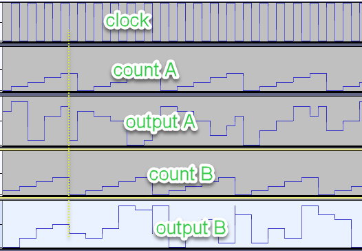
Figure 10. Clock, internal counters, and random outputs
To play different WAV files through the WaveOneShotPlayerFlash1 module at run time, we must:
Use an ArraySet module to update the WAV fileName in module WaveOneShotPlayerFlash1.
Delay the WaveOneShotPlayerFlash1’s trigger to allow time for the WAV file to be loaded.
This is described in more detail in the WaveOneShotPlayerFlash application note.
Trigger Generator

Figure 11. Trigger Generator
The Rand Sequencer’s output A is routed to a 1-sample delay. Output A and the delayed output are then compared. This results in a 1-sample wide pulse every time A changes.
Because these are control signals (indicated by the dotted lines connecting modules), they are set to a block size of 1. Turn on Wire Info and Accumulated Delay under the “View” menu to see the details.
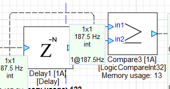
Figure 12. Generating a trigger when the output changes
This will create a trigger pulse that is 1 block in length (due to the Block Size being 1 sample and the delay setting also equal to one sample). The Block Time is set by the input pin, which is 256 samples (Block Size) / 48000 (Sample Rate) = 5.333 milliseconds. This corresponds to a Block Frequency of 187.5 Hz.
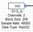
Figure 13. Input Pin Properties
The 187.5 Hz Sampling Rate was entered into the Arguments tab of DC3.
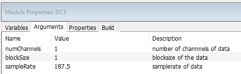
Figure 14. DC3 Arguments - sampleRate
Wave File Selector
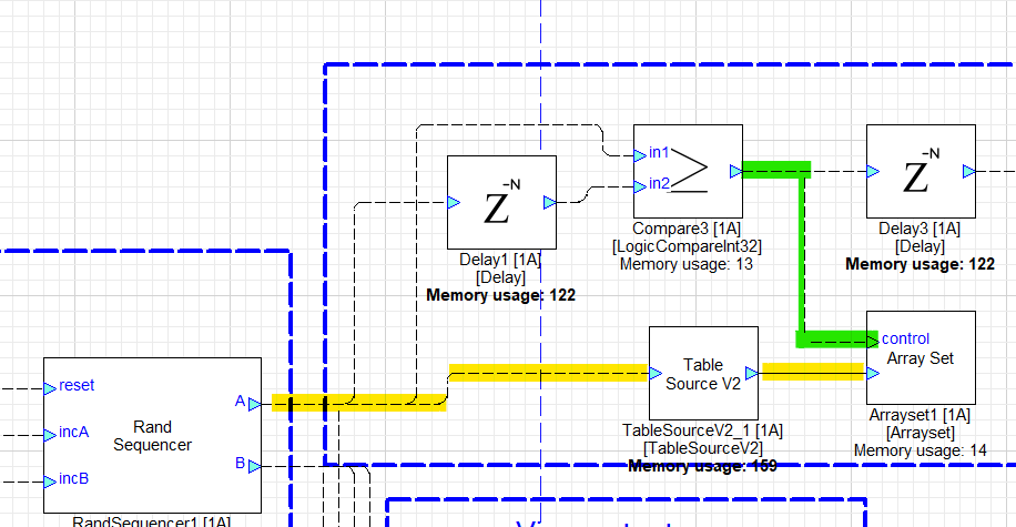
Figure 15. Setting the WAV file name
The 1-sample width pulse coming out of the comparator loads the selected encoded WAV file name from the TableSourceV2 into WavePlayerOneshotFlash1’s fileName variable.
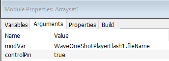
Figure 16. Arrayset1 Properties
Delayed Trigger to Wave Player
When the fileName of the WaveOneShotPlayerFlash1 module is updated by the ArraySet1 module, a delay is required before you can reliably trigger the new WAV file. The amount of delay depends on:
Platform – CPU speed, memory access specs
System load – multithreaded design defers lower priority tasks such as file loading
WAV file – longer files take longer to load
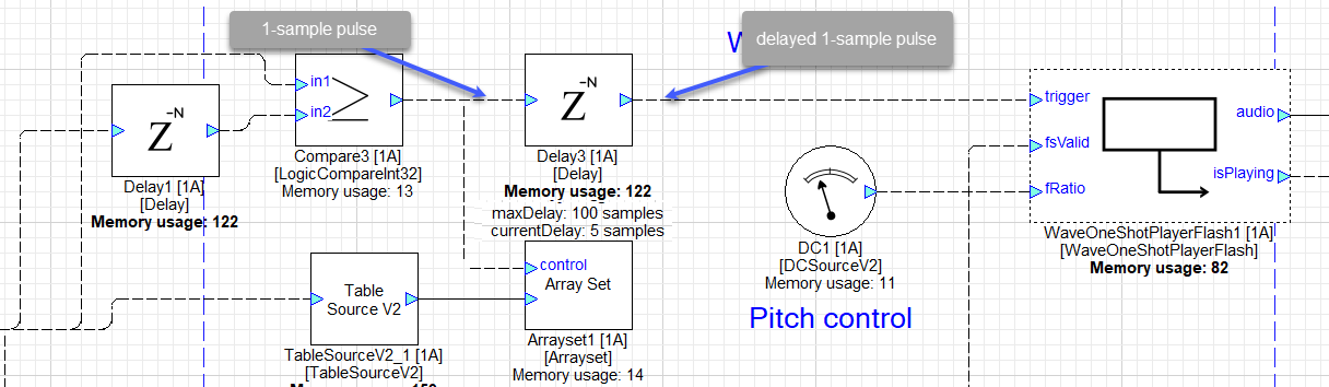
Figure 17. Delaying the trigger
This delay was set to 5 samples on a test Windows machine using the short WAV files provided in the sample. When the delay was set to 1 sample, playback fails intermittently. The delay time will need to be adjusted on your target system.
The waveforms below show the RandSequencer’s B output changing, followed by the delayed trigger pulse to the WavePlayerOneShotFlash.
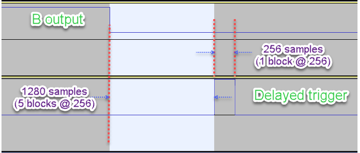
Figure 18. Timing Diagram
The WavePlayerOneShotFlash module
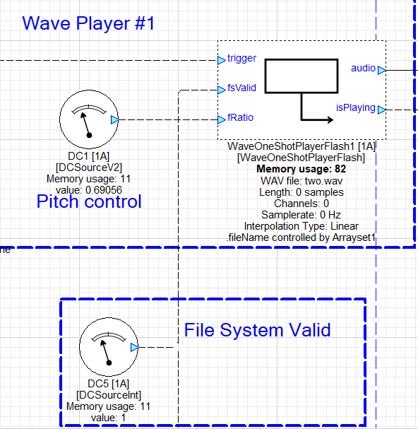
Figure 19. WavePlayerOneShotFlash module
Pin | Description |
trigger | Starts playback of the selected WAV file. |
fsValid | Indicates the file system is valid. May be delayed on some embedded platforms, in which case it is the host’s responsibility to manage this signal. |
fRatio | Playback pitch ratio |
audio | Audio output |
isPlaying | Optional pin to indicate that playback is in progress. |
The reference layout includes an optional Sink Display so that you can visualize the state of the flags while listening to the running layout. In a real embedded system, these signals could be monitored by the host for more intelligent trigger management.
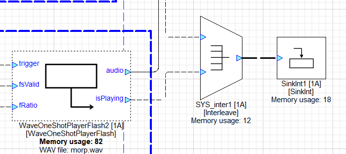
Figure 20. isPlaying signal
View outputs A & B
Another optional Sink Display is added so that you can watch the Rand Sequencer's A and B outputs while listening to the audio output.
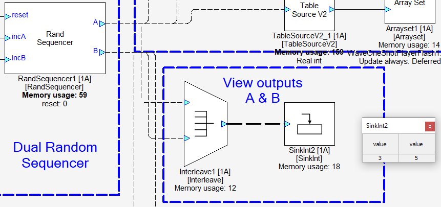
Figure 21. View Outputs A & B
1
I