
Router
Overview
Channel routing without smoothing
Discussion
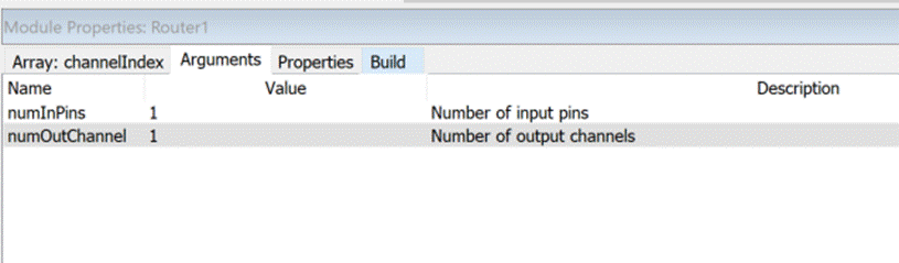
The router_module.m is an intelligent copier and combines several channels from different wires into a new multichannel wire. The module can have multiple input pins but only a single output pin. At instantiation time, you specify the number of input pins and number of output channels.
M = router_module(NAME, NUMINPIN, NUMOUTCHANNEL)
The module has an internal array channelIndex[] of integer values. The array has length NUMOUTCHANNEL values and value N specifies the mapping from input pin and channel to output channel N. Keep in mind that all indexes (both for pins and channels) are zero based.
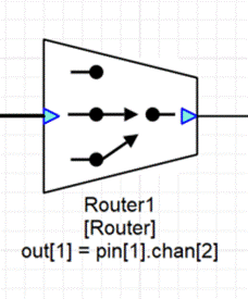
The channelIndex integer is a packed 32-bit value
channelIndex = (pinIndex << 16) + (channelIndex)
or alternatively
channelIndex = 65536 * pinIndex + channelIndex.
If channelIndex is incorrectly set and the encoded pinIndex or channelIndex are out of range then the module will mute the corresponding channel. The Router module performs a straight copy of data and supports all 32-bit data types. The Router module is ideal for fixed routing configurations. If you want to make changes to the routing table at run-time, you should use the smoothly varying RouterSmoothed and RouterSmoothedFract32 modules.
The module’s use will become clear through several examples.
Example #1 — Selecting a single channel
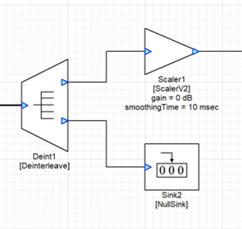
This is wasteful because it requires 3 modules to do what a single router module can do. Create a Router with 1 input pin and 1 output channel.
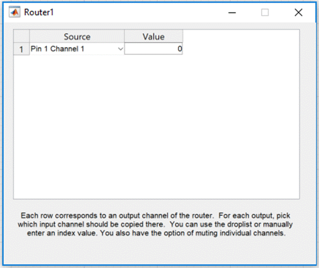
The desired left output channel is on pin 0 and channel 0 so set .channelIndex to 65536 * 0 + 0 = 0.
The system only requires a single Router module now:
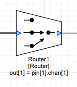
If instead you want to pass the right channel, set channelIndex to 65536*0 + 1 = 1. The string shown on the canvas will update showing you the specified channel ordering:
Example #2 — Selecting 2 channels
Suppose you have a 5.1 signal with channels ordered: L, C, R, Ls, Rs, LFE. If you want to form a new stereo signal with just the L and R channels, use a router with a single input pin and 2 output channels. Then set the channelIndex values to:
channelIndex[0] = 65536 * 0 + 0 = 0
channelIndex[1] = 65536 * 0 + 2 = 2
If instead you want to extract the Ls and Rs signals, use:
channelIndex[0] = 65536 * 0 + 3 = 3
channelIndex[1] = 65536 * 0 + 4 = 4
Example #3 — Swapping left and right channels
The output channels do now have to be in the same order as the inputs. For example, suppose you had a stereo signal and you want to swap the order of the left and right channels. Create the Router module with 1 input pin and 2 output channels. Then set:
channelIndex[0] = 65536 * 0 + 1 = 1
channelIndex[1] = 65536 * 0 + 0 = 0
Example #4 — Deleting a channel
Suppose you have a 5.1 signal with channels ordered: L, R, C, LFE, Ls, Rs. If you want to form a new 5 channel signal that excludes the LFE channel you would use a Router module with 1 input pin and 5 output channels. Then set the channelIndex array to:
channelIndex[0] = 65536 * 0 + 0 = 0 // L
channelIndex[1] = 65536 * 0 + 1 = 1 // R
channelIndex[2] = 65536 * 0 + 2 = 2 // C
channelIndex[3] = 65536 * 0 + 4 = 4 // Ls
channelIndex[4] = 65536 * 0 + 5 = 5 // Rs
Example #5 — Inserting a channel
Let’s continue the previous example. Suppose that you processed the LFE channel separately and now want to combine the 5 channel signal (L, R, C, Ls, Rs) with a separate LFE and form the signal (L, R, C, LFE, Ls, Rs). You could do this with a Router module. Configure the Router so that it has 2 input pins and 6 output channels. The first input pin attaches to the 5 channel signal and the 2nd output pin attaches to the LFE. The channelIndex array is then configured as:
channelIndex[0] = 65536 * 0 + 0 = 0 // L
channelIndex[1] = 65536 * 0 + 1 = 1 // R
channelIndex[2] = 65536 * 0 + 2 = 2 // C
channelIndex[3] = 65536 * 1 + 0 = 65536 // LFE
channelIndex[4] = 65536 * 0 + 4 = 4 // Ls
channelIndex[5] = 65536 * 0 + 5 = 5 // Rs
Type Definition
typedef struct _ModuleRouter
{
    ModuleInstanceDescriptor instance;            // Common Audio Weaver module instance structure
    INT32* channelIndex;                          // Specifies input to output channel routing. Each item in the array corresponds to an output channel and contains two packed values: input pin number in the high 16 bits; input channel number in the low 16 bits.
} ModuleRouterClass;
Variables
Properties
Name | Type | Usage | isHidden | Default value | Range | Units |
channelIndex | int* | parameter | 0 | [1 x 1] | Unrestricted |
Pins
Input Pins
Name: in1
Description: Input signal
Data type: {float, int, fract32}
Channel range: Unrestricted
Block size range: Unrestricted
Sample rate range: Unrestricted
Complex support: Real and Complex
Output Pins
Name: out
Description: Output signal
Data type: {float, int, fract32}
MATLAB Usage
File Name: router_module.m
 M=router_module(NAME, NUMINPIN, NUMOUTCHANNEL)
 Creates a router module for use in the Audio Weaver environment, which
 selects channels from multiple input pins and combines them into a single
 multichannel output.

 Arguments:
    NAME - name of the module.
    NUMINPIN - number of input pins.
    NUMOUTCHANNEL - number of interleaved outputs. There is a single
         output pin.