
Wave File Sink and Source
About This Guide
This application note describes the usage and workings of Wave File Source Module and Wave File Sink Module.
Wave File Source Module
The Wave File Source module opens and reads audio data from an input .wav file and streams it over the output wire. The module can be found in Source->Advanced->Wave File Source in the Module Bar on the left-hand side of AudioWeaver Designer.
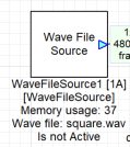
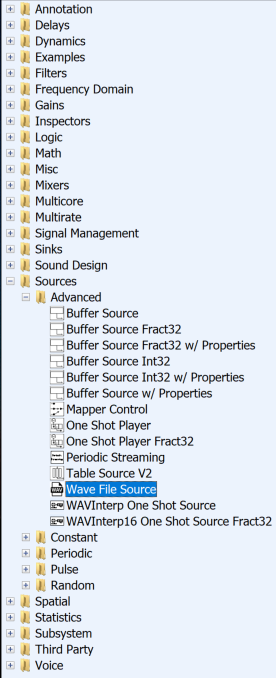
Figure 1: Wave File Source Module and Location
Arguments:
Arguments can be found Rt Click View Properties second tab in the properties as shown. The following table shows the list of arguments in the Wave File Source module, explanations along with their respective default values.
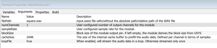
Figure 2: Wave File Source Module arguments
Arguments | Description | Default Value |
filePath | Input path / name of the wave file source | By default, WAVFILE = ''. |
blockSize | Number of samples per output channel. | By default, blockSize = Derives from SYS_in. |
sampleRate | Sample rate of the output signal, in Hz. | By default, SAMPLERATE = Derives from SYS_in. |
numChannels | Number of output channels for the module. | By default, numChannels = Derives from SYS_in. |
cacheSize | The size of the internal buffer to prefill the audio data. | By default, 2048 |
loopFile | Streams audio data in loop. Otherwise streamed only once. | By default, true. |
Workings
The example in the figure below shows two Wave File Source modules. WaveFileSource1 has a square wave file generated at 1kHz and WaveFileSource2 has Sine tone wave file at 1kHz. The file can be input via filePath argument. We can observe the files combined from both the wave source channels in Sink3. As seen below both sine and square waves can be observed. Double clicking the Wave file Source module during runtime, we can seen initDone as ‘1’ and number of channels in the wave file along with the Sample Rate of the wave file.
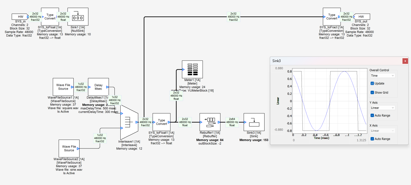
Figure 3: Wave File Source Example
Any problems in the module will be indicated by errorCode inside the inspector.
Error Code | Explanation |
-1 | File fopen command error (output.wav) |
-2 | File fread command error (output.wav) |
-3 | File fwrite command error (output.wav) |
-4 | File fseek command error (output.wav) |
-5 | File already exists / File name already used by another module in the layout |
-6 | File fopen command error: No such file or directory |
-7 | File fopen command error: Out of memory |
-8 | File fopen command error: write permission is denied |
-9 | File fopen command error: read-only file system and mode requires write |
Wave File Sink Module
The Wave File Sink module opens and reads audio data from an input .wav file and streams it over the output wire. The module can be found in Sinks->Wave File Sink in the Module Bar on the left-hand side of AudioWeaver Designer.
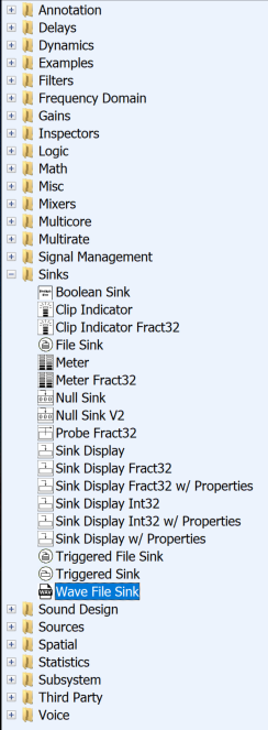
Figure 4: Wave File Source Module and Location
Arguments:
Arguments can be found Rt Click View Properties second tab in the properties as shown. The following table shows the list of arguments in the Wave File Sink module, explanations along with their respective default values.
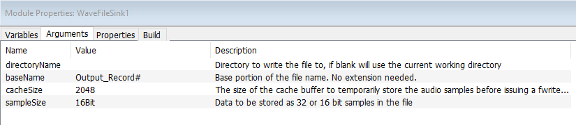
Figure 5: Wave File Sink Module Properties
Arguments | Description | Default Value |
directoryName | Directory to write the file to | By default, WAVFILE = ''. |
baseName | File name without extension | By default, baseName = “Record#” |
cacheSize | Size of cache buffer to store the audio samples. | By default, cacheSize = 2048 |
sampleSize | Data to be stored as 32- or 16-bit samples in the file. | By default, 16Bit |
Workings
The example in the figure below we are playing a square wave at channel 1 and a sine wave at channel 2 from the input. The Wave File Sink is used to record and verify the input file being fed from the SYS_in. As seen figure 7 which is the recorded file from the module, we can verify that ch1 is a sq wave and ch2 is a sine wave.
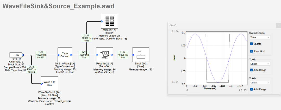
Figure 6: Wave File Sink module example
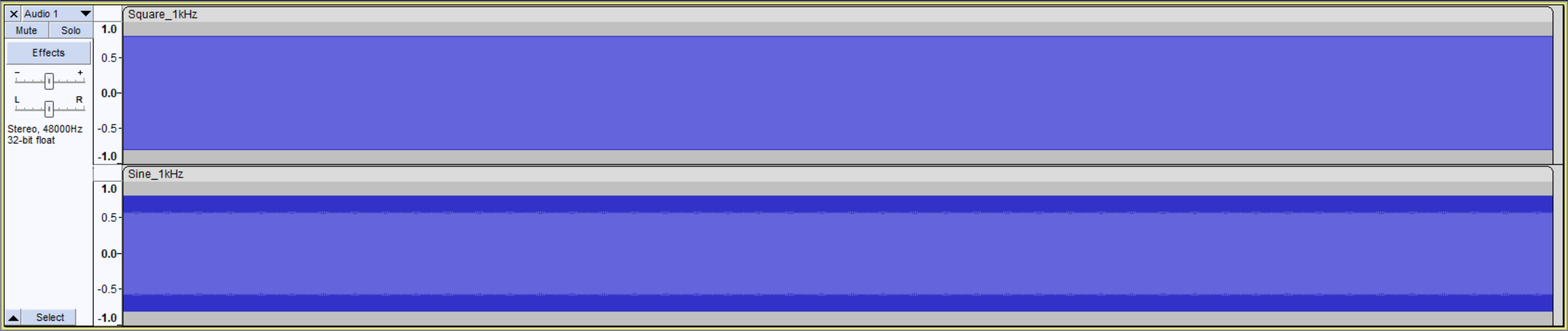
Figure 7: Input File (ch1: square wave, ch2: sine wave) from SYS_in
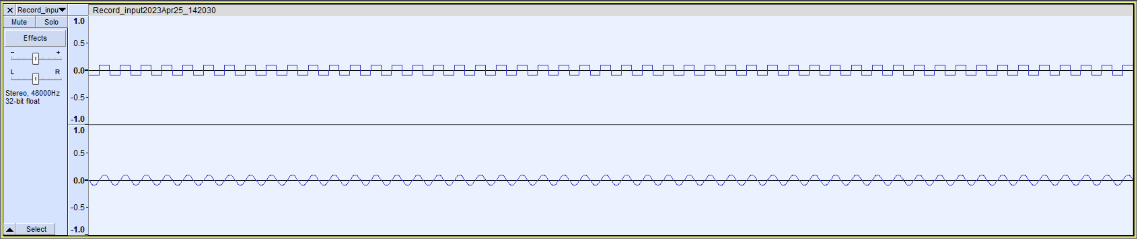
Figure 8: Recorded Wave file at WaveFileSink1
Block by Block Processing of Wave File Sink and Source
In this section we will look at block by block processing of the wave file sink and wave file source module via input and output pins. For this AWE Pro version is required. Open the WaveFileSink_Source-Process Files.awd in the AWE Designer. In this example we have the Wave File Sink connected to the input channels. Input an appropriate path for the files to be recorded in the Wave File Sink module. The Wave File Source is playing a 20Hz Sine Tone wave file and is connected to the Output. To start the example first run the WaveFileSink_Source-Process Files.awd.
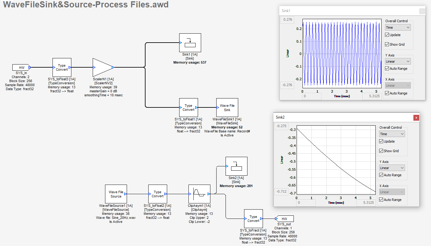
Figure 9: Wave File Sink and Source - Block by Block Processing
In the same folder we have the MATLAB code ‘WaveFileSink_Sourceprocess_example.m’ used for block-by-block processing. As seen below the code generates a Sine Chirp for 100 blocks and pumps it into the input pin. The Wave File Sink records and saves the generated 100 blocks of the input signal of the sine chirp. The Sine Tone at 20Hz played by the Wave File Source in the awd is processed inside the MATLAB code by via the line
[SYS, WIRE_OUT] = process(SYS, WIRE_IN, 1);
Both the input and output signal are plotted in the end.
% This script tests calling the MATLAB processing functions
% It works in Native mode or on a target

%GSYS = load_awd('Example - Process Files.awd'); % Will load directly from Disk

% If the system is open in Designer, get it directly.  This is faster
% than load_awd().
GSYS = get_gsys('WaveFileSink_Source-Process Files.awd');

SYS = GSYS.SYS;

lv.TOP_BLOCKSIZE = 32;


SYS.targetSpecificInfo.RT = 0; % 0 for non-real time build
% Non-real time build does 2 things:
% This forces the input and output buffers to not be double buffered
% And you no longer have to match the fundamental block size of the system


% ==============================================
% Make a chirp signal
% ==============================================
blockSize = SYS.inputPin{1}.type.blockSize;
numChannels = SYS.inputPin{1}.type.numChannels;
SR = SYS.inputPin{1}.type.sampleRate;

% Generate the input data
NUM_BLOCKS = 100; % chirp signal is 100 blocks long

L = NUM_BLOCKS * blockSize; % 256 * 100

n = 0:(L-1);
n = n(:);
T = n/SR;

% Starting and ending frequencies of the chirp, in Hz.
f0 = 20;
f1 = 5000;
X = chirp(T,f0,max(T),f1,'logarithmic', -90);
X = repmat(X, 1, numChannels); % duplicate to make stereo

% Build the system.  On PC or on the target
SYS=build(SYS);

% ==============================================
% Make a chirp signal
% ==============================================

if (0) % 0 or 1
    % Process everything in one call if 1
    WIRE_IN = {X}; % X is input data.  Turn into system input wire
    [SYS, WIRE_OUT] = process(SYS, WIRE_IN, NUM_BLOCKS); % call process function, tell how many blocks, and give input data
    Y = WIRE_OUT{1};
else
    % Process block-by-block if 0
    Y = [];
    for i = 1:NUM_BLOCKS % loop over all the blocks
        if (i == 10) % if we're at block number 10, change the master gain to -12
            % Make a tuning change
            SYS.ScalerN1.masterGain = -12;
        end
        startIndex = (i - 1) * blockSize + 1; % Start index of data
        endIndex = startIndex + blockSize - 1; % End index of data
        WIRE_IN = {X(startIndex:endIndex, :)}; % Get data out of the input array from the correct indexes (get both channels)
        [SYS, WIRE_OUT] = process(SYS, WIRE_IN, 1); % Process 1 block, and get SYS object back, get wire output
        fprintf(1, 'Processing block %d of %d\n', i, NUM_BLOCKS); % 100 blocks, 1 block at a time
        if (isempty(Y)) % Accumulate all the wire output into Y, 1 block at a time
            Y = WIRE_OUT{1};
        else
            Y = [Y; WIRE_OUT{1}];
        end
    end
end

% Plot data
figure;
subplot(211);
plot(X);
title('Input Plot');
subplot(212);
plot(Y);
title('Output Plot');
After starting the awd run this MATLAB file. The MATLAB file on completing gives a plot of Input and Output signals as shown below.
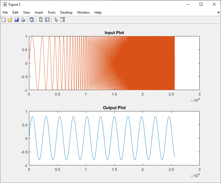
Figure 10: MATLAB Processed Plot
The shows processed Input signal i.e., Sine Chirp generated by the MATLAB code and played into the SYS_IN. The sine chirp played via the input is then captured by the wave file sink module and saved on the device. The saved file is shown below, which matches the Sine Chirp generated.
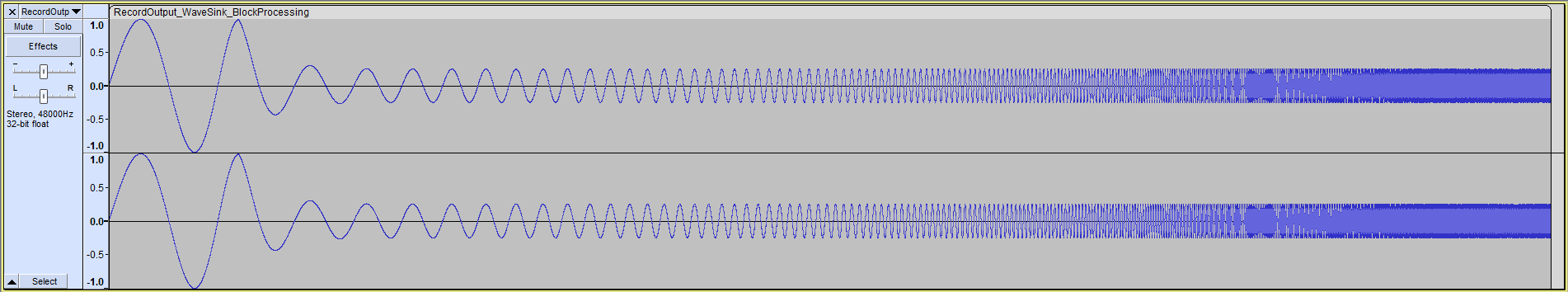
Figure 11: Saved file from Wave File Sink
WaveFileSink_Sourceprocess_example.m WaveFileSink_Source-Process Files.awd