Control Interface Usage and Debugging
About This Application Note
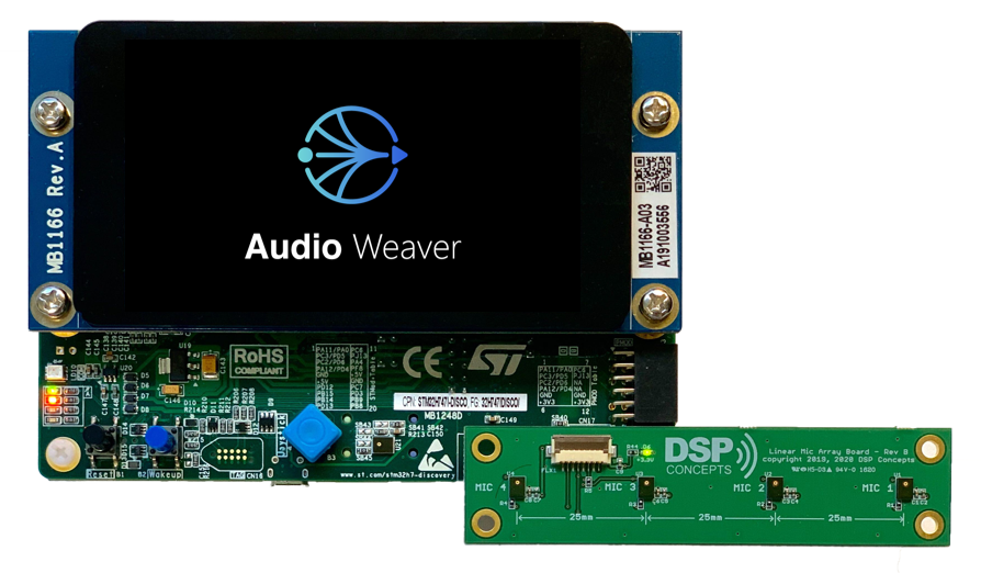
This application note explains and demonstrates usage of Audio Weaver’s Control Interface API. To help illustrate this, we include sample code from DSP Concepts' Audio Weaver STM32H747I-DISCO (ARM Cortex-M7) discovery kit (EVK) board support package (BSP) and utilize the IAR Embedded Workbench for Arm compiler for project navigation and runtime behavior.
This guide assumes that the reader has a basic understanding of Audio Weaver and C programming. While the example code references are hardware specific, the general process of Audio Weaver’s Control Interface usage and debugging is applicable to all embedded bare metal targets.
Building and flashing a BSP with IAR Embedded workbench for Arm
The BSP used in this example is “awe8-bsp-stm32h747i-discovery-single-core”
In IAR, select File -> Open workspace in IAR. The “STM32H747i_Discovery.eww” project file is located in <REPO LOCATION>\SampleApp\STM32H747i-SingleCore\Build\EWARM
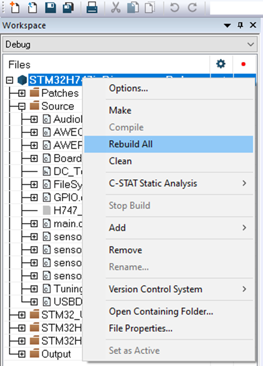
Rebuilding the BSP can be performed by right-clicking the workspace name and selecting “Rebuild All”
The build will output a .bin file located in “<REPO LOCATION>\SampleApp\STM32H747i-SingleCore\Bin\EWARM\” which can be flashed when not debugging by using the STM32 ST-LINK Utility software. Contact support@dspconcepts.com for more information.
Connect the Discovery Board to the PC via both the USB OTG_HS and ST-LINK V3E ports with USB micro cables then select “Download and Debug” from the IAR toolbar. (Ensure the JP6 jumper on the bottom of the board is set to HS)
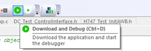
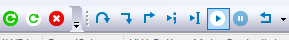
Once flashed, run the code with the “play” button. From here, breakpoints can be set in the code, and variables can be watched for debugging.
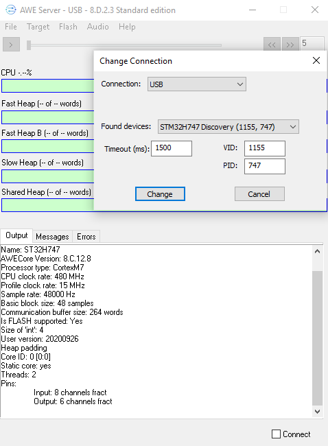
By default, main.c will run AWEIdleLoop() located in AWEplatform.c. At this point the board should be seen by the AWE Server, able to connect, a run a design in Tuning Mode.
Generating Target Files to Run a Design
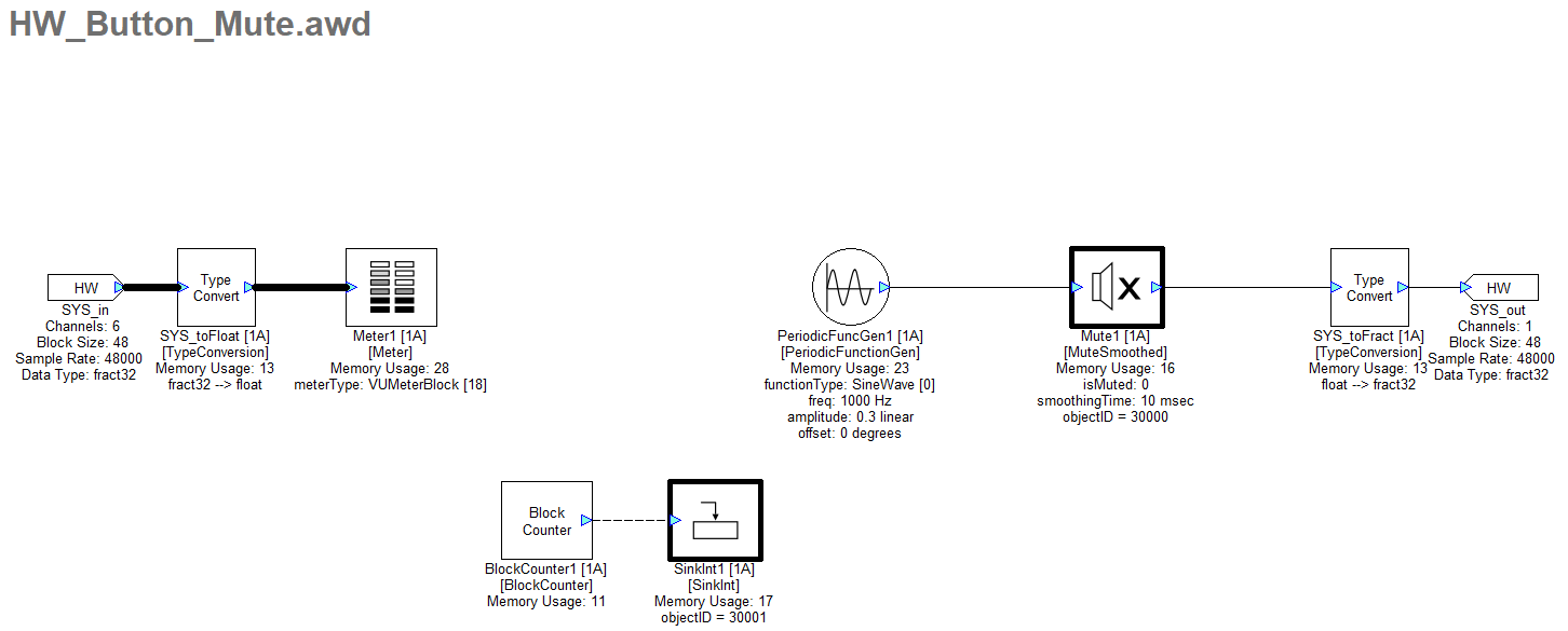
An example .awd is attached to this Application Note. It is a simple design which outputs a sine tone. Using the control interface API we’ll set up hardware control so while the blue “wakeup” user button on the STM32H747 is pushed, the sine tone is muted awe_ctrlSetValue()and a blue LED illuminates. Additionally, the value of a block counter within the design will be queried with awe_ctrlGetValue() and toggle an orange LED every 500 blocks.
For the control interface to access parameters of a module, the module will need to have an ObjectID assigned. An objectID can be assigned as an integer between 30000 and 32767. In the screenshot below, SinkInt and Mute1 have been assigned objectIDs which is indicated by the bold border. Set the objectID of a module in the build tab of its properties.
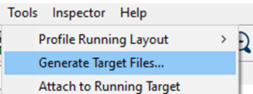
With the design to be exported open in Designer, go to Tools -> Generate Target Files
Check the appropriate boxes to generate the .awb, .h, and .c files.
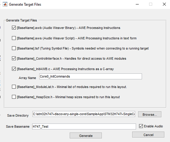
Export an .awb, ControlInterface.h, and InitAWB.c files. (InitAWB.h will be generated automatically)
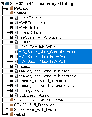
Copy the generated C and header files to the Source files path in your project.
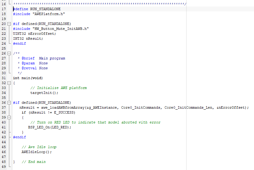
In main.c define RUN_STANDALONE (line 17) and include “HW_Button_Mute_InitAWB.h” (line 21). This will instruct the board to load a design on startup in standalone mode. When compiled, the code will call awe_loadAWBfromArray() which references the “Core0_InitCommands” array generated previously from Designer.
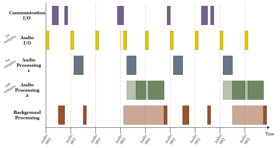
After loading the AWB array, AWEIdleLoop() is called. In the idle loop context, non-real-time tasks are processed as a low priority background task. This includes the processing of tuning commands, deferred processing, and any Control command processing, as opposed to audio processing which should be set as the highest priority. Tuning interface commands flow between Designer and the target, whereas Control interface commands flow between the firmware and .awb running on target (e.g. volume knob or other hardware controls and user modes)
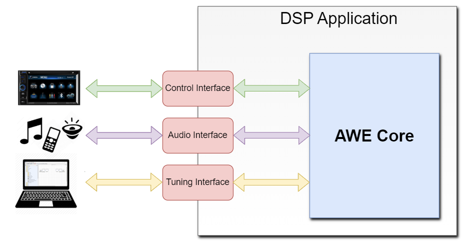
A dynamic view of the execution and pre-emption of these tasks is shown below. The lightly shaded areas mean that the task has been triggered but is not currently executing because it has been pre-empted by another, higher priority task. Note that priority order is configured by the app/BSP writer.
Include “HW_Button_Mute_ControlInterface.h” in AWEPlatform.c. For this example we’ll also declare some variables for the control interface steps.
//Add these 5 lines for Application Note Example
#include "HW_Button_Mute_ControlInterface.h"
UINT32 buttonState;
UINT32 lastButtonState;
UINT32 runTime;
UINT32 classID;
UINT32 muteStatus;
Using the Control Interface with the STM32H747
Note: Additional Control Interface and API documentation here:
https://w.dspconcepts.com/hubfs/Docs-AWECore/AWECore_API_Doc/index.html#ctrl-interface-overview
https://w.dspconcepts.com/hubfs/Docs-AWECore/AWECore_API_Doc/a00082.html
The below code was added to AWEIdleLoop() in AWEPlatform.c
First, check if the module exists and is of the right class with awe_ctrlGetModuleClass(). Then use one of the awe_ctrl functions to set/get something about a module. We get the AWE_Mute1_isMuted_HANDLE and AWE_Mute1_classID variables from "HW_Button_Mute_ControlInterface.h" which is also where AWE_OBJECT_FOUND is defined.
In this example we check the state of the blue (wakeup) user button on the board. If the button is pushed changing from 0 to 1, the mute module’s “isMuted” parameter is set to 1, and a blue LED is turned on while the button is pushed.
Similary, in the next section of code, we query a SinkInt module’s value which returns the number of blocks processed since the design began running. An orange LED is toggled every 500 blocks.
//Control I/O
//If the Mute module is found...
if (awe_ctrlGetModuleClass(&g_AWEInstance, AWE_Mute1_isMuted_HANDLE, &classID) == AWE_OBJECT_FOUND)
{
  //...check that the module assigned this classID is of module class Mute
  if (classID == AWE_Mute1_classID)
  {
    //If the blue button on the board is pushed, mute the output in the design and turn on the Blue LED
    awe_pltGPIOGetPin(1, (UINT32 *)&buttonState);
    if (buttonState != lastButtonState)
    {
      awe_ctrlSetValue(&g_AWEInstance, AWE_Mute1_isMuted_HANDLE, (void *)&buttonState, 0, 1);
      BSP_LED_Toggle(LED_BLUE);
      lastButtonState = buttonState;
    }
  }
}


if (awe_ctrlGetModuleClass(&g_AWEInstance, AWE_SinkInt1_value_HANDLE, &classID) == AWE_OBJECT_FOUND)
{
  if (classID == AWE_SinkInt1_classID)
  {
    //Read the "SinkInt" value from the design for total runTime(48bs) and toggle every 500 blocks
    awe_ctrlGetValue(&g_AWEInstance, AWE_SinkInt1_value_HANDLE, (void *)&runTime, 0, 1);
    if (runTime % 1000 > 500)
    {
      BSP_LED_On(LED_ORANGE);
    }
    else
    {
      BSP_LED_Off(LED_ORANGE);
    }
  }
}
We can add a line of code to “get” or “set” the status of a module and store it into a variable with the following:
awe_ctrlGetStatus(&g_AWEInstance, AWE_Mute1_isMuted_HANDLE, (void *)&muteStatus);A helpful option while debugging is to “watch” variables. While running the code, highlight and right click any of the variables to “add to watch” to view a watched variables value in real time as you step through code.
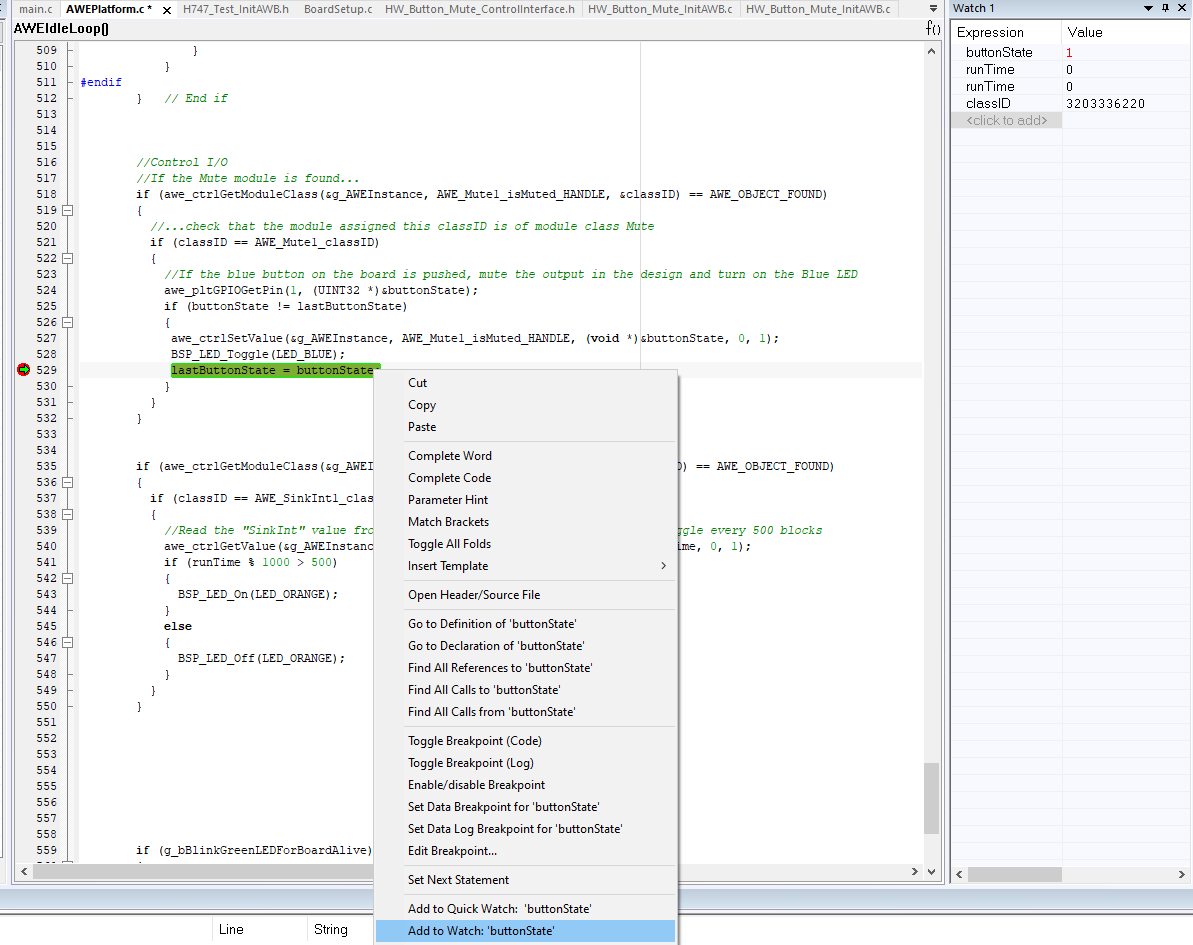
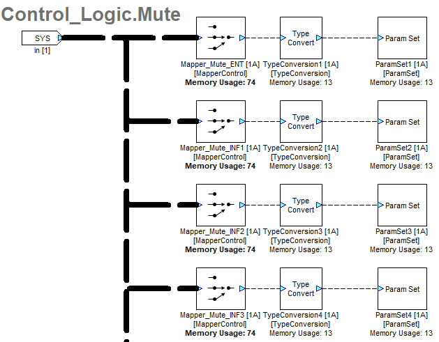
Note: If many parameters are being sent via the control interface, it is advisable to send all parameters as a single array to a single Buffer Source module in the design. In the screenshot below, a BufferSourceInt module named “Control_IPC_In” receives an array from the application code, then outputs to a Control_Logic subsystem for next steps.
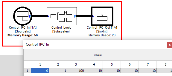
Once the array is received in the design, Mapper and ParamSet modules can be used to route specific array indices to the correct module parameters.