
Subsystems
Create Subsystems to Add Hierarchy
Subsystems can be used to organize your layout into coherent groups. You can navigate through the different hierarchies either with the tabs at the top of the canvas, or with the ‘Navigate Up’ or ‘Navigate In’ right-click menu options in the Designer GUI.
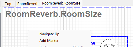
Right click on canvas
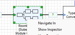
Right-click on Subsystem
Convert To Subsystem
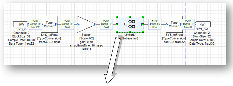
If you are working on a layout which is starting to get crowded, you can create a subsystem from an existing group of modules. To do this, select a module or set of modules, right click, then select the Convert To Subsystem option. This replaces the selected modules with a new subsystem that contains the selected modules.
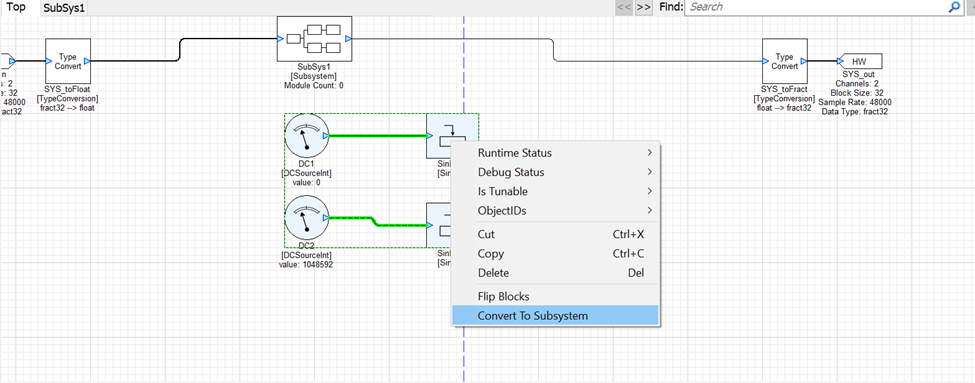
Convert To Subsystem
To create an empty subsystem, drag out the Subsystem module from the Subsystem folder, then double click or right click and select ‘Navigate In’ to design the internal system. By default, a new Subsystem has one input pin and one output pin. If more I/O is needed, add System Input and Output pin modules from the Subsystem folder of the module browser.
User Inspectors
Subsystems created entirely within Designer can have one or more user created inspectors, also built within Designer, to control the subsystem operations. The user inspector is shown differently depending on where in the subsystem hierarchy the user is.
Adding a user inspector changes the double-left-click behavior of a subsystem.
Without a user inspector, double clicking opens the subsystem on the screen.
After you have added a user inspector, double clicking will show the user inspector, whether the layout is running or not.
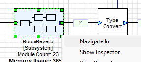
“Navigate In” and “Show Inspector” are always available from the right-click menu.
When the user inspector is at the same hierarchical level as the user view, it can be opened for edit mode when double clicked. Note “DOUBLE-CLICK TO EDIT” is shown in the module Variables.
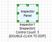
The inspector can be modified to change or display variables from the modules in the subsystem.
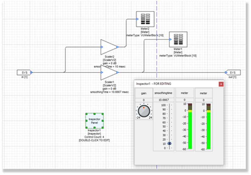
In the previous example, the inspector edit dialog is invoked by double clicking the Inspector module on the canvas. The dialog will say “FOR EDITING”. In editing mode, controls are not active. If you click on a control in editing mode, you can drag it to a new location or resize it.
In order to change the variables in the attached modules from this level, one must use the right click menu on the canvas and choose “Show Inspector”. This is also valid for User Inspectors at the top level of the diagram.
Creating a User Inspector
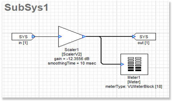
In this example, a subsystem has been created with a ScalerV2 module and a Meter module. The desire is to have a knob to control gain, and a meter to show the output level.
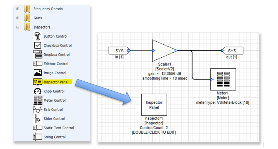
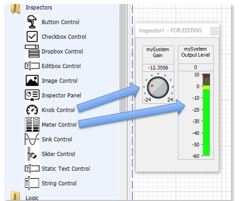
The scaler module and meter module are necessary to attach to the knob control and meter control. First, select “Inspector Panel” from the module palette under the “Inspectors” heading.
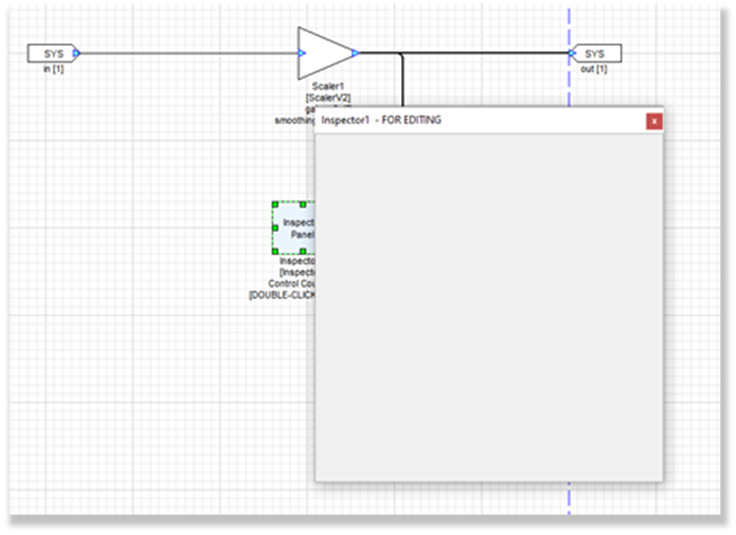
Drag the Inspector Panel onto the canvas. Double click the Inspector Panel to edit, a blank Inspector Panel will open in Edit Mode as in the following figure. Edit Mode can be used to add, delete, move or change properties of inspector controls.
Drag a knob and meter inspector control from the palette:
If the editable user mode dialog is not large enough to accommodate the default size of the control, it cannot be placed – increase the size of the Inspector Panel, then retry placement.
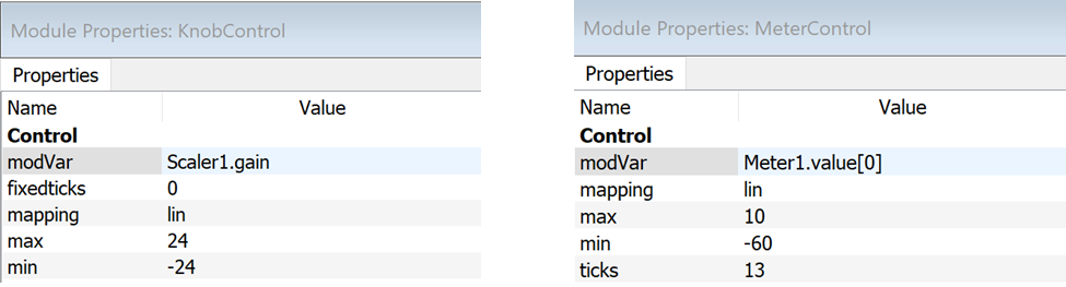
Before testing the dialog, one must attach the control to a module variable. Right click on the meter and knob controls in the Inspector Panel and click View Properties in the pop-up menu. Enter Scaler1.gain in the modVar field, and Meter1.value[0] in the modVar field of the meter. If the names of the modules were changed after placement, enter those names instead of Scaler1 and Meter1:
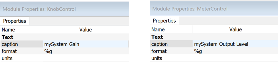
Use the caption property to change the displayed name of each control:
For more information on each inspector control and their available properties, see the descriptions in the Property panel, or right click either in the module browser or in the Inspector panel and click Help.
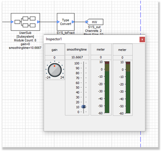
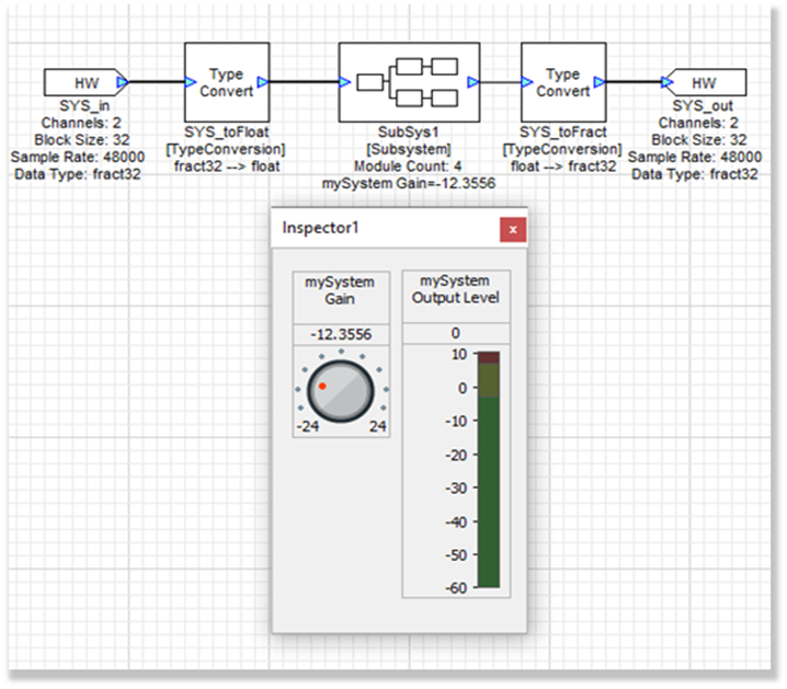
Next, ascend the hierarchy to the top level, where double clicking the subsystem will now show the inspector dialog in Control Mode. Control Mode can be used during design time or run time to change the values of the module variables linked to each inspector control. For example, the knob control will change the subsystem’s gain module variable. The subsystem module block will show updates of the values as in the next figure:
This user subsystem, complete with an inspector, can be saved to the module palette and shared with other designs as a reusable subsystem, as described in the next section.
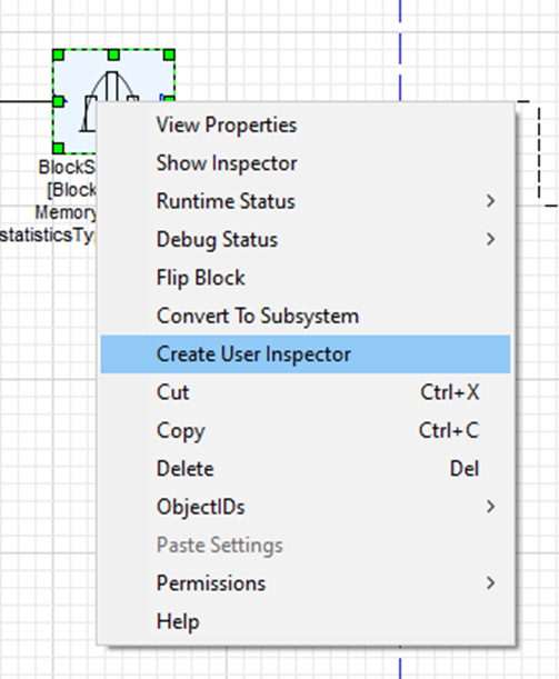
As a starting point, a user can right-click a module and select “Create User Inspector” to create a new Inspector Panel with the controls for this module.
Reusable Subsystems
A “Reusable Subsystem” allows a user to design a subsystem with a custom set of modules/user inspectors, and then save and reuse that subsystem across any layout. The reusable subsystem is represented by XML and MATLAB files that are generated when the reusable subsystem is created. The reusable subsystem can be shared by distributing these files and adding the MATLAB search paths accordingly via Designer.
Converting a Subsystem to a Reusable Subsystem
To create a Reusable Subsystem, begin with a regular subsystem. Create the subsystem (see Create Subsystems to Add Hierarchy), and make sure that it will build and run without errors. Tweak the modules as needed and add any desired User Inspectors. Ensure that any contained modules that access another module’s variable (eg. ParamSet, ParamGet) DO NOT reference modules that are outside the subsystem.
There are two ways to convert this subsystem module into a Reusable Subsystem. From the top level layout:
Click and drag the entire subsystem module from the canvas and to the Module Palette, either on an existing module directory or in the empty space, or
Right-click the subsystem module and select the “Create Reusable Subsystem” option.
A new dialog window appears, titled “Create New Reusable Subsystem”, with the following entry fields (see figure below). Complete and edit these fields accordingly for this Reusable Subsystem:
Root Directory - root folder for the Reusable Subsystem’s generated folders/files (see Generated Folders/Files)
Class Name - Unique file name for the generated output files.
Browser Path - Category in which module will appear under in the module palette
If the subsystem was dragged onto an existing module directory in the Module Palette, this will be automatically populated with that existing directory name. Otherwise, this will be automatically populated with the new directory name “Reusable Subsystems”.
Browser Name - The name of the module that will appear in the module browser
Canvas Legend - The text which will appear in the reusable subsystem block when on the Canvas.
Search Tags - Search terms to locate this module in the Module Browser
Pin Data Types - Valid data types for module input pins (can select multiple types)
Compiled Subsystem – If checked, creates a Compiled Reusable Subsystem
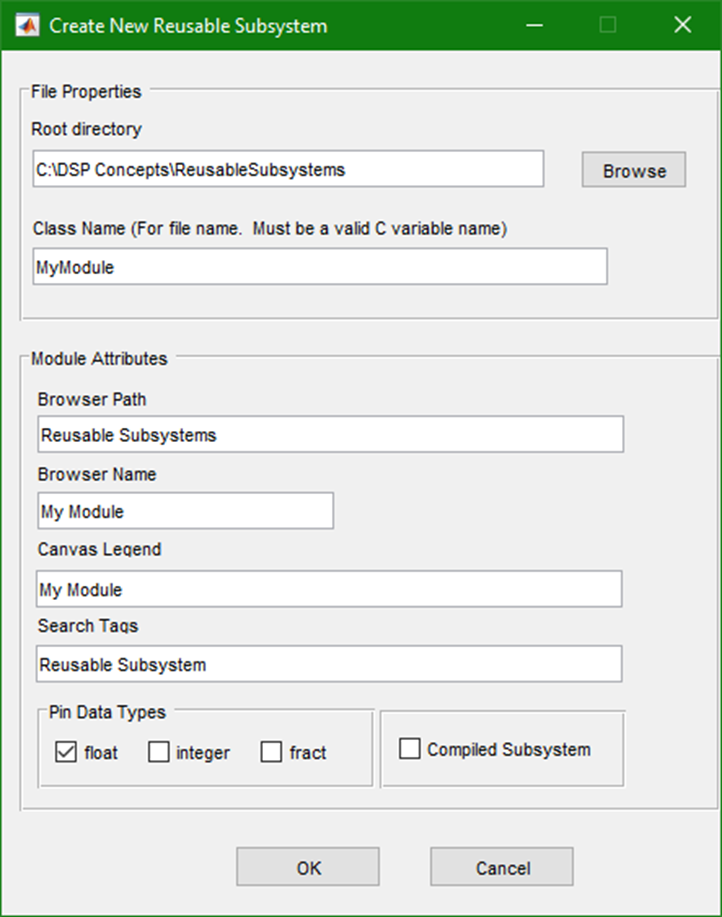
Dialog box for Creating a New Reusable Subsystem
Once the fields are set, click OK, and the Reusable Subsystem will be created.
Note: The standard subsystem is not automatically replaced with the new reusable subsystem on the canvas. This action is left to the user to drag out to the canvas needed.
Generated Folders/Files
When a user clicks OK and creates a new Reusable Subsystem, Designer generates the necessary output files and folders, and adds them to the appropriate MATLAB paths. The location of this generated output depends on the Root Directory that was entered at creation time. This folder structure should not be modified by the user to ensure the Reusable Subsystem’s compatibility with Designer. See below for information about the generated output.
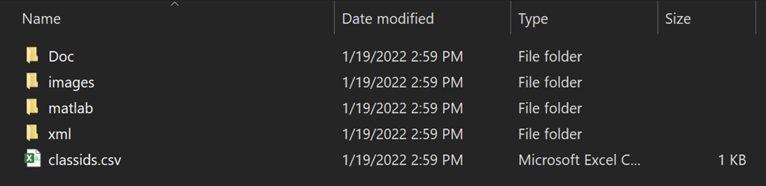
Doc
This folder is where HTML help documentation is located, which is an auto-generated template file that the user should update as described below:
Headings, formatting, names of Inspector Controls and pins will be pre-populated, but it will be up to the user to fill in other information. The template will be populated with keywords that can be replaced with the user’s desired text. These will be:
$description$: A short description of the module in one sentence.
$discussion$: Longer, detailed description.
Inspector Control description keywords will have the format $<ctrl_caption>Description$ e.g. an inspector control with the caption Left Gain would be $LeftGainDescription$
Pin description keywords will have the format $<pin_name>Description$
Lastly, the required modules will be included. This does not expose internal tuning or wiring, just which modules must be present in the AWE Core library on the target for the subsystem to function.
An example Python script for automating the html template replacement:
def replaceTemplate(filePath):
    varMap = {
        "$description$": "MyGreatModule makes awesome sounds",
        "$discussion$": "Using proprietary technology, MyGreatModule knocks your socks off with booming bass, harmonious highs and magnificent mids.",
        #"$MagicButtonDescription$": "Push this to hear the magic!"
    }
    with open(filePath, 'r') as fid:
        fileContents = fid.read()
    for templateVar in varMap:
        fileContents = fileContents.replace(templateVar, varMap[templateVar])
    with open(filePath, 'w') as fid:
        fid.write(fileContents)
images
The default bitmap image (Default.bmp) will be used as the default Module Palette icon for all Reusable Subsystem modules. You can change this icon by either editing Default.bmp image, or by creating a new icon and updating the XML file:
Create a new .bmp image file for the Reusable Subsystem. Place this file in this images/ directory.
.bmp file dimensions must be 32-by-32 pixels, at 24 bit depth. Any other size will not be displayed properly in Designer’s Module Palette.
Edit the XML file to replace the filename with your new .bmp. Do not change the filepath otherwise. For example:
<image>../images/MyModule.bmp</image>
Reopen Audio Weaver Designer and search for the reusable subsystem in the Module Palette.
The icon should appear next to the reusable subsystem in the Module Palette.
By default, the image of the reusable subsystem will be blank with only the “Canvas Legend” text. The image of the reusable subsystem on the Designer canvas can also be changed using a custom SVG file.
Create a new SVG file for your Reusable Subsystem. Place this file in this images/ directory.
Edit the XML file to replace the filename with your new .bmp. Do not change the filepath otherwise. For example:
<svgimage>../images/MyModule.svg</svgimage>
If you don’t want the text displayed across SVG image in the Canvas, delete the text in between the <legend> tags.
Reopen Audio Weaver Designer and search for the reusable subsystem in the Module Palette.
The icon should appear next to the reusable subsystem in the Module Palette.
Click and drag the Reusable Subsystem onto the Canvas. The SVG will be displayed on the Reusable Subsystem.
MATLAB
The .json file represents the reusable subsystem in a text file format, used for construction
(Compiled Reusable Subsystems only) The .awb file contains the compiled reusable subsystem in an encrypted binary format
(Compiled Reusable Subsystems only) The .meta file contains definitions of any controlled module variables (eg. custom ObjectIDs, User Inspector Controls) within the subsystem
xml
The xml layout of the module used by Designer GUI. This is auto-generated and should not be modified, except when adding user-contributed images for the Reusable Subsystem.
Any manual edits to the XML files will not be preserved when making updates and overwriting a Reusable Subsystem (see Modifying a Reusable Subsystem and Overwriting).
Reverting a Reusable Subsystem
To revert a Reusable Subsystem back to a regular Subsystem, simply right click the Reusable Subsystem block on the canvas and select “Revert to Subsystem”. Now, the subsystem can be opened and modified accordingly.
Note: This right-click menu option is not available for Compiled Reusable Subsystems.
Modifying a Reusable Subsystem and Overwriting
To modify an existing Reusable Subsystem, start by converting it back to a regular Subsystem (see Reverting a Reusable Subsystem). Make the desired changes, and when complete, simply drag the block back onto the existing reusable subsystem entry in the module browser. The dialog window will open, and click OK to overwrite the existing reusable subsystem, or you can specify new entries to create an additional new module. The user should delete any previous creations of this Reusable Subsystem from the layout, as it could be unusable after the Reusable Subsystem is updated.
Reusable Subsystem “User Inspectors”
A Reusable Subsystem will maintain a User Inspector panel during reuse. Simply create the desired user inspector panel (see Creating a User Inspector) and be sure that all the inspector’s modVar properties are set to modules within the Reusable Subsystem. Create the Reusable Subsystem in the same way, and the inspector panel will be saved along with it.
Compiled Reusable Subsystems
Compiled Reusable Subsystems are Reusable Subsystems with backing files that are compiled to a binary format (.awb). Compiled Reusable Subsystems are similar to non-Compiled versions with the following key benefits:
The binary format means the layout does not need to be dynamically built, thus leading to faster layout build times (see Module Wiring).
The binary format is encrypted when creating the Compiled Reusable Subsystem, providing privacy for users interested in protecting their IP.
The compiled format has higher memory overhead on the target, and there are more supplemental files (see Generated Folders/Files) when compared to regular Reusable Subsystems.
Reusable Subsystems Limitations
Reusable Subsystems have a few special cases which should be noted.
As previously stated, any modVar access must occur between modules in the same subsystem.
Any Inspector Groups will be removed (inspector groups are separate from User Inspector panels, which will be saved alongside a reusable subsystem).
The following limitations only apply to Compiled Reusable Subsystems:
The subsystem module must be fully connected/wired within the layout for the Compiled Reusable Subsystem creation to complete.
The Compiled Reusable Subsystem cannot be reverted to a regular subsystem.
The subsystem must be single-threaded and cannot contain any clock-divided modules like BufferUp / BufferDown.