Threading and Clock Dividers
About This Application Note
The Threading and Clock Dividers Application Note contains instructions for using multiple block sizes within a single system, the modules necessary to do so, and the effects of doing so with respect to latency and priority handling.
Clock Divider
The ClockDivider field in Properties when left blank will default to 1A0. This represents clock divider “1”, Thread (subLayoutID) “A” and instance “0”. The instance value can be changed to move that module to a designated core (4 virtual cores by default in Designer [0,3]) and profiled separately. The clock divider changes as a result of buffering up or down.
(Multi Instance only): The instanceID of an AWE command is determined by the instanceID of a module/wire in the design. The instanceID is a propagatable field, and can be modified using the 'ChangeThread' module, or, for a source module, by setting the clockDivider field in the build tab of the module properties. The syntax to set the clockDivider field is <clockDivider (#)><threadThead (letter)><instanceID (#)>, so '2B3' will run the source module with clockDivider of 2, on thread B of instance 3. The 'ChangeThread' module exists to take one or more input wires of data that exists on one instanceId, and send it to another user-specified instanceId.
Note: The clock divider field is only user editable for source modules and automatically assigned for the rest.
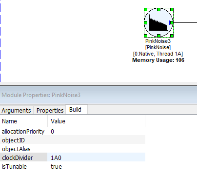
For example, if 1A0 were changed to 1A1, profiling for that module would could be seen on the second instance on the Server:
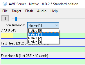
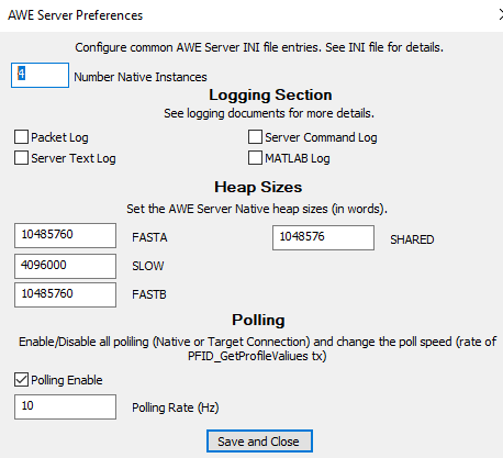
Note: By default, 4 virtual instances are created in Designer Native. These can be changed in Server Preferences, and memory will be divided between them. If only one core is designated, the clock divider will not display the instance number, but just subLayoutID and Clock Divider:
The same clock divider can be used by up to 16 layouts (called as threads A to P). i.e. first layout with clock divider 1 will have thread id of 1A, second layout with the same clock divider of 1 can have thread id of 1B and so on up to thread id of 1P, using BufferUpV2 module.
Buffer Up and Buffer Down
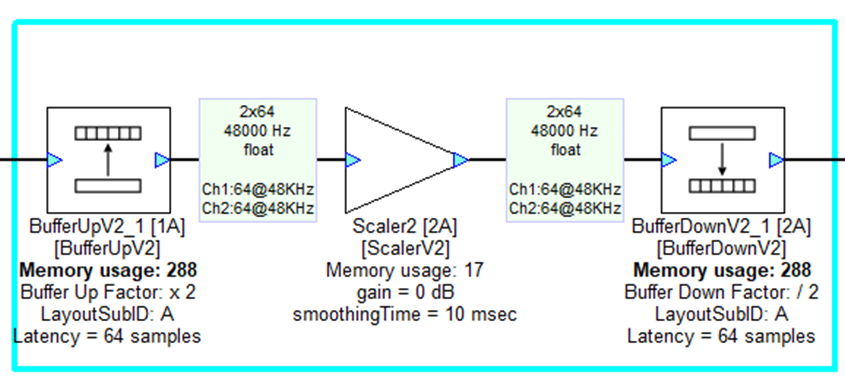
To change block sizes within a design, Buffer Up creates a new layout within Audio Weaver and is used in conjunction with Buffer Down. This layout will appear as a continuation of the signal flow in the same design file, however the portion of the system between Buffer Up and Buffer Down will operate at a different block size (whole number multiple of the input block size) and in a different layout, designated in the module’s properties tab.
The thread, (or layoutSubID) allows you to run multiple sets of modules at the same clockDivider in different layouts by setting the block size, and layoutSubID. For instance, the system input pin is always in layout 1A, and any layouts with the same clock divider could reside in 1B, 1C, alphabetically up to 1P. By changing to a higher block size, the user would be creating a second clock divider, where the user can add up to 16 layout subIDs in this new block size (2A, 2B, 2C, etc.).
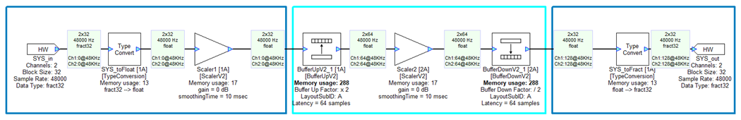
When you build a layout like this, Audio weaver will split it into two layouts. The layouts are processed in separate threads because they have different block sizes.
The higher priority layout will execute the far left and right sections of the system
The lower priority layout will execute the middle section of the system
Buffer Up
Increases block size, creating a new layout with a designated layoutSubID
The Buffer Up module supports multiple input and output pins
The input wires must all be in the same clock divider
This module introduces a sample latency of buffUpFactor times the input pin’s block size
Large clock dividers go into lower priority layouts
User can designate layouts ‘A’ through ‘P’ (16 total)
Supports buffering up by whole-number multiples
More information on BufferUpV2 available here: BufferUpV2
Buffer Down
Ends a layout and returns to the original clock divider (higher priority, smaller block size)
Decreases input block size by whole-number multiple
Introduces a sample latency of the input pin’s block size
Latency effects of Multithreading
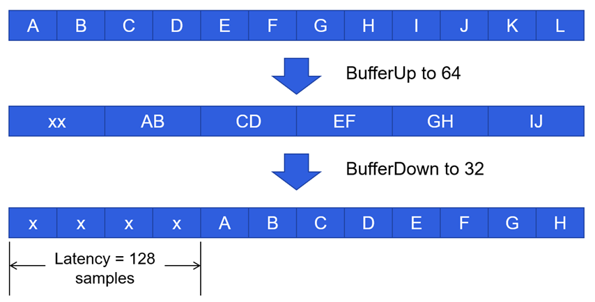
When a system’s block size is multiplied X times to buffer up, the smaller block size portion of the layout will need to run X number of times to fill the higher block size buffer. Additionally, when buffering down, the larger block size will pump smaller portions to the lower block size X number of times. Shown in Figure 2.0, buffering up incurs 64 samples of latency, then buffering down incurs another 64 samples, for a total of 128. At a sample rate of 48kHz, this would amount to 2.6ms of latency.
Processing Priority
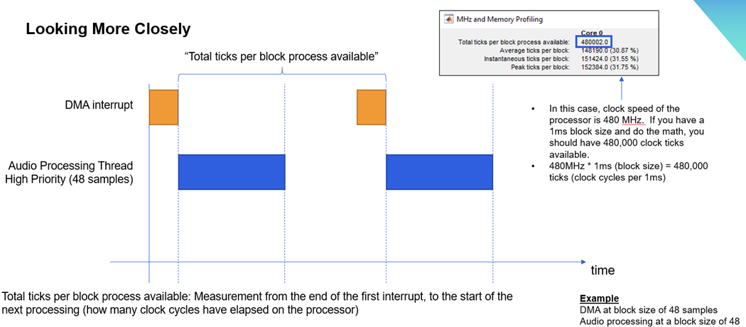
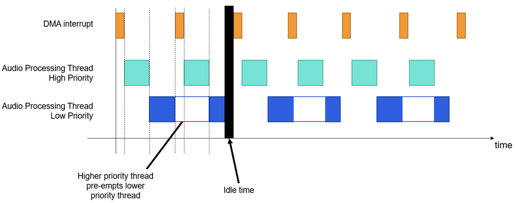
The high priority thread will be given however many ticks are needed between DMA interrupts, before the lower priority thread is able to be processed. If the lower priority thread is not finished processing before the next DMA interrupt, processing will be paused until the next time the high priority thread is finished processing.
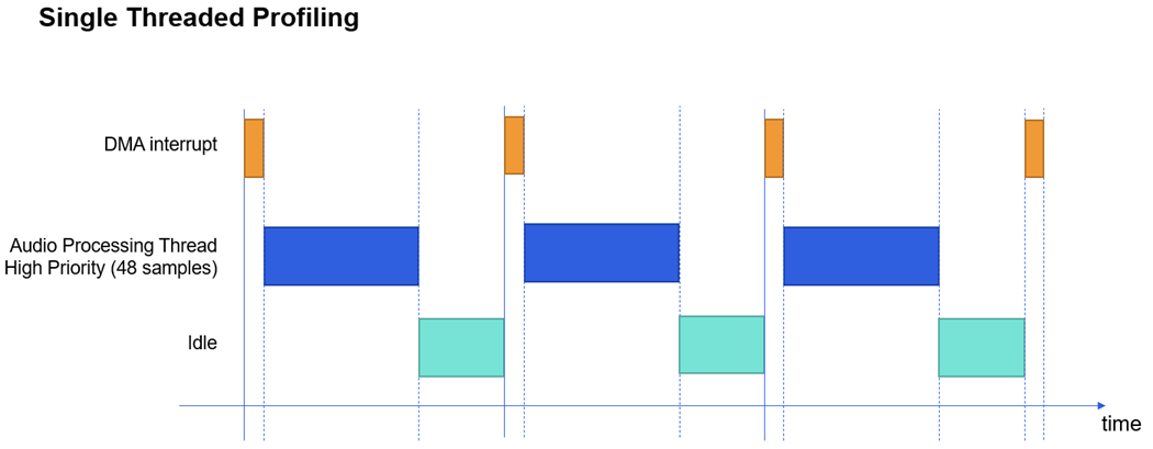
Profiling
In the example below, a system with a block size of 48 samples is run on a processor with a clock speed of 480 MHz.
With a sample rate of 48,000 Hz, each block will take 1 ms to process.480 MHz * 1 ms = 480,000 ticks per block process available.