
Module Wiring
Module Wiring Information
The wires that connect modules together can show detailed information about the data that is being passed through them. Wire information is updated for the whole layout when ‘Propagate Changes’ or the ‘Build and Run’ buttons are pressed in Designer. The ‘View’ menu in Designer can be used to individually enable and disable the different display options shown below:
Showing Wire Information
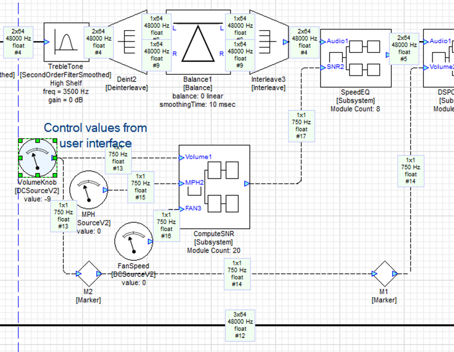
To prevent visual clutter, the wire information display is by default disabled in Audio Weaver, but this information can be useful to display while designing or debugging a system. To show the wire information for each wire on your canvas, select ‘View 🡪 Wire Info’ menu item on the Audio Weaver toolbar banner. When selected, each wire will display the number of channels, block size, sample rate, data type, and the auto-assigned wire number. ‘2x64’ means two channels and a block size of 64 samples, and a ‘C’ added to the end of the data type means that the data is complex.
If the information panel shows a question mark (‘?’) for a wire, then it means that the layout failed to completely propagate wire information due to an invalid module configuration. Hit ‘Build and Run’ to throw the error message for the invalid module.
Channel Names
Wires connecting modules in a layout may consist of multiple channels. These channels can be named to help track which data stream is being sent where. This can be very helpful for designs with a large amount of IO channels. To show all the channel names in a layout, select ‘View → Channel Names’. Channel names can also be shown for a specific wire by hovering over the wire with the mouse.
Assigning Channel Names
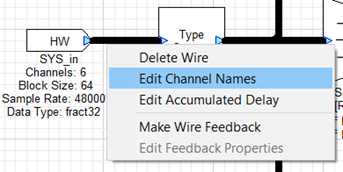
To assign names to channels, right click on a wire and select “Edit Channel Names”.
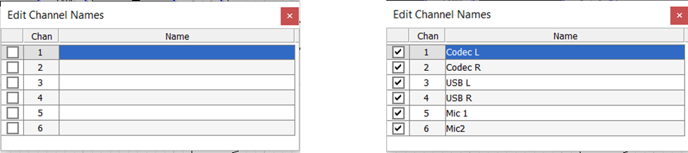
Hit ENTER and start typing channel names. Each time ENTER is pressed, the focus will move to the next row. The checkbox in the leftmost column toggles between inheriting the channel name (unchecked) and defining a new channel name (checked). The right image below has renamed all 6 channels on the wire, and the left image has inherited all the empty channel names.
Inherited Channel Names
Once channels have been named, the channel names on a module input wire may be propagated to module output wires. To view inherited names in the edit channel names dialog uncheck the checkbox.
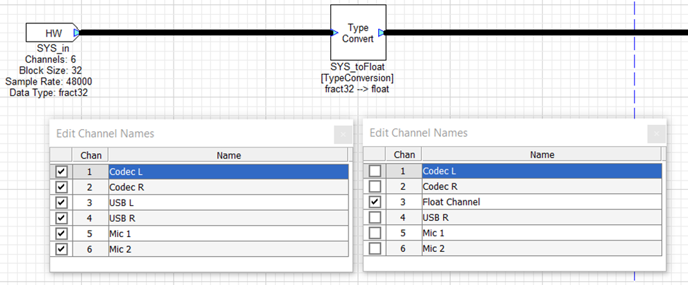
Above the channel names were defined for the input wire going into the Type Convert module. The output wire of the Type Convert module has inherited the channel names from the input wire and we have defined a new channel name for channel 3 “Float Channel”.
Viewing Channel Names
Whether channel name display is enabled for the whole layout, or if just hovering above one pin, the channel names are displayed above the wire as in the image below.
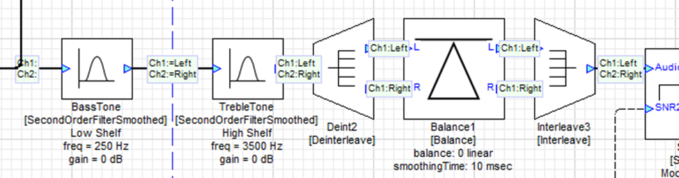
Regardless of whether there is an assigned name, every wire will show the characters ‘Ch#:’ for each channel on that wire. This is displayed in order to help identify which channel number on the wire each name corresponds to. In the image above, the channel names ‘Left’ and ‘Right’ are respectively assigned to channel 1 and channel 2 in between the ‘BassTone’ and ‘TrebleTone’ modules. The wire display in between these modules provides the additional ‘=’ decoration before the assigned channel name in order to show that the channel names were assigned to this wire. All the wires downstream will inherit the ‘Left’ and ‘Right’ channel names and do not have the ‘=’ decoration.
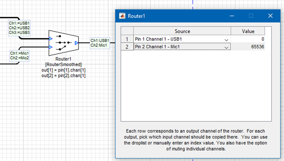
The channel names assigned to wires will also be shown in some module inspectors to make it more obvious which channel is being interacted with. For example, the Router module will show the channel names in the channel selection drop downs in its inspector:
Accumulated Delay
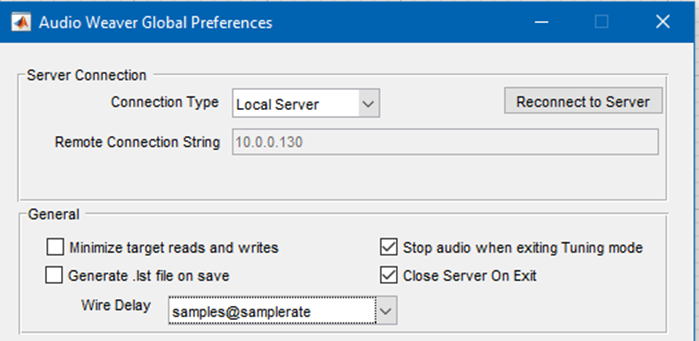
The wires in Designer also store information about the total delay of the signal through the system. This delay value can be displayed with the ‘View → Accumulated Delay’ menu item. By default, the delay will be shown in units of samples at the specified sample rate. The units can be changed to milliseconds of delay using the ‘Wire Delay’ dropdown of the ‘File -> Global Preferences’ menu:
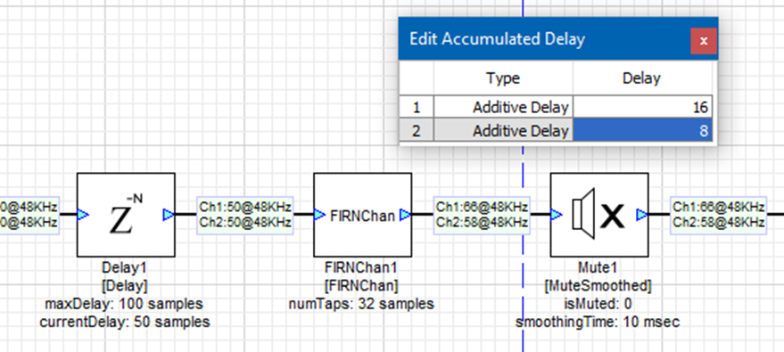
Once enabled, the wire information shown for a system will look something like this:
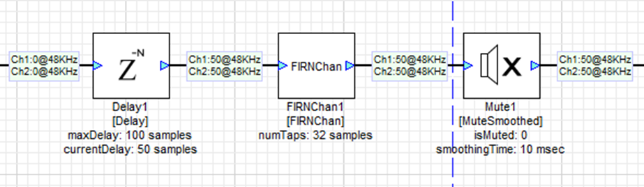
Since the delays can be different for each channel on a wire, the ‘Ch#:’ string is provided to indicate that the following delay value applies to the #th channel on the given wire. In the image above, the Delay module introduces 50 samples of delay to each channel on the 48KHz wire, as seen by the ‘50@48KHz’ in the wire information display. There is also an FIR module in the flow that introduces latency to both channels, but the FIR module is not able to calculate the latency by the user supplied coefficients. To account for this latency, right click on the wire after the FIRNChan module and click ‘Edit Accumulated Delay’:
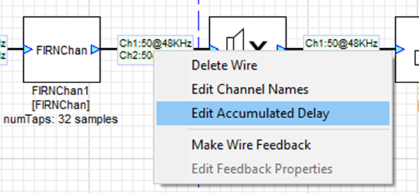
In the menu that opens up, the user can choose to continue to inherit the delay from upstream wires, add a fixed value to the inherited delay, or override the inherited delay with a new value. The coefficients supplied to this FIRNChan module introduce a 16 sample delay to the first channel, and an 8 sample delay to the second channel, so the wire information is edited as below:
Changing Input Pin Properties
Right-click on the HW input pin to change its number of channels, Block Size and Sample Rate properties. Once the model is run or the ‘Propagate Changes’ icon is clicked, the updated HW pin information will propagate through the rest of the system. The output HW pin information is inherited from the connecting wire and cannot be edited manually.
Note: The dataType of the input pin is fract32 and cannot be changed.

Feedback Wires
In an Audio Weaver layout, data typically flows from the input towards the output, with the output of one module feeding the input of one or more modules after it in the processing order. However, it is possible to feed the output of a module back to the input of a module that precedes it in the processing order. In this case, the new data will not be processed until the next block of data is processed resulting in a delay of one block. In AWE Designer, such feedback wires need to be specified manually. To do this, right-click on a wire and select ‘Feedback’ from the context menu:
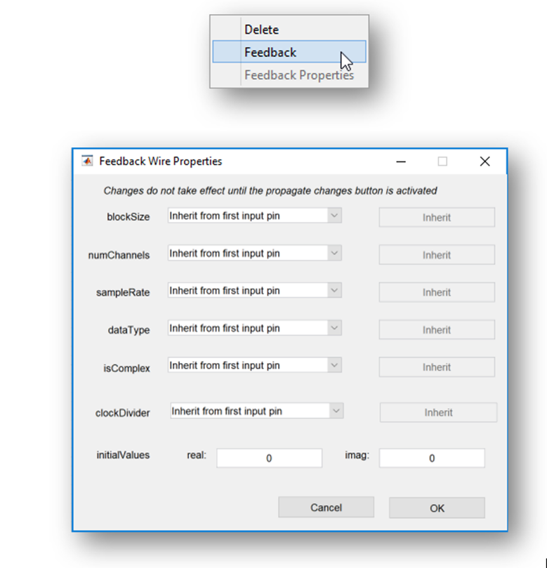
The properties of the feedback wire can then be specified as either to be related to the properties of the layout’s input pin, or a custom value. See Feedback Wires for a detailed explanation of this feature.