Multirate processing
About this guide
There is an overview of multirate modules here. This guide provides additional details about working with multirate designs in Audio Weaver.
Reasons for making the sampling rate lower
Part of your algorithm may be operating with a naturally reduced bandwidth, e.g. the lowpass output of a crossover, or a dedicated voice channel operating at e.g. 16 kHz while the music channel is running at 48 kHz. By reducing the sampling rate to twice this reduced bandwidth, you will save half of the CPU cycles used for processing this part of your algorithm. Since the up and down sample rate conversions also consume CPU cycles, you may wish to test the CPU utilization of your layout both with and without sample rate conversion to see which has the lowest CPU utilization.
You may be trying to use a third party module, such as voice recognition, which comes configured to process audio at a lower fixed rate. The documentation for the third party library should include this information. This scenario may not require upsampling afterwards if you are not listening to the voice channel through the system’s audio outputs, only using it for voice recognition.
Reasons for making the sampling rate higher
If you are trying to perform accurate filtering near the Nyquist frequency (sampling rate/2), you may encounter issues with filter accuracy or stability. By increasing the sampling rate (oversampling) by a factor of 2, the frequencies in question are now closer to the subsystems (Nyquist frequency/4), and the resulting filter’s results are more predictable.
If you are applying non-linear processing to a signal, such as using the “Soft Clipper” on a guitar signal, harmonics will be generated which can easily result in aliasing. By upsampling the signal first, the generated harmonics will have additional space in the spectrum before they hit the Nyquist frequency and start aliasing.
Reasons for making the Block Size larger
Some modules use Fast Fourier Transforms (FFTs) to generate a frequency spectrum of the signal. The number of points (equally spaced frequencies) in the result is equal to the number of samples which you transform at any given time. Therefore, if you perform an FFT using a block size of 16 samples, your frequency spectrum will only have 16 equally spaced bands across the entire range from 0 Hz to (sampling frequency/2). This may not be sufficient resolution for your needs, in which case you need to increase the block size to match the number of desired points on the frequency response plot.
Some modules use FFTs “behind the scenes” to improve processing efficiency. Larger gains in efficiency are gained by using larger block sizes. Here’s an example.
When you want to visualize the audio waveform somewhere in your layout during debugging, the native block size may not show enough of the waveform. The “Rebuffer” module should be used as needed.
Reasons for making the Block Size smaller
The main reason to make the block size smaller is to convert the data back to the system’s native block size, previously having made the block size larger as described above.
See the use of the SubBlockStatistics Module as well.
Multi-layout and multiple sample rates
The term “layout” is used throughout Audio Weaver documentation to refer to “a group of modules and connections implementing an audio algorithm”. When you load an AWD file, you are loading the layout. When you generate an Audio Weaver Script (AWS) file (Tools->Generate Target Files) for deployment onto your embedded device, a single AWS file is created.
Within the generated AWS file you will find descriptions of the modules and connections. Each distinct section containing modules running at a different block time will generate a “create_layout” command within this script. So, “layout” or “sublayout” is also used to refer to a section within a design which runs at a different clock frequency as the input pin.
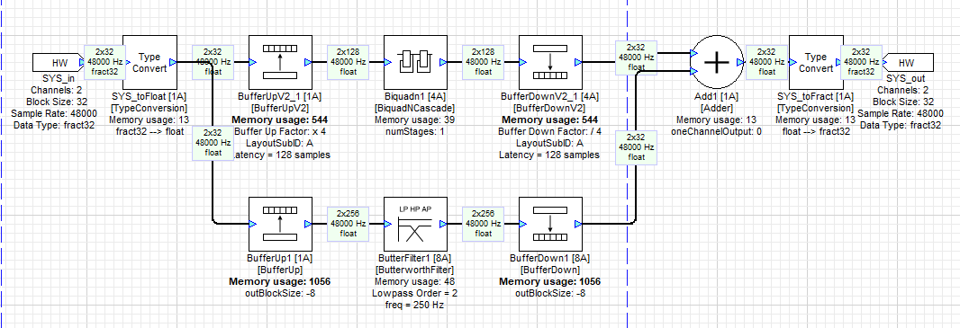
For example, the following layout includes 3 separate block times, 1A, 4A, and 8A. These numbers indicate the block time relative to the input pin at the input of the module in question.
The generated AWS file includes 3 corresponding “create_layout” lines, as shown:
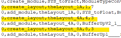
See this page for additional details on threading and clock dividers.
Need for integer interpolation and decimation factors
Decimation
Decimation (for reducing the sampling rate) incorporates both lowpass filtering to suppress any content above the target reduced sampling rate’s Nyquist frequency, as well as subsequent downsampling, which operates by dropping existing samples. To reduce the sampling rate by 2, every other sample is dropped. To reduce the sampling rate by 3, 2 out of every 3 samples are dropped. In general, to reduce the sampling rate by M, (M - 1) out of every M samples should be dropped (and should follow the same pattern). Since this approach operates on whole samples (i.e. you can’t drop 1.5 samples), the decimation factor in the module’s Properties has to be an integer.
Modules which use downsampling
Downsampler
No filtering
Decimation factor D should be a positive integer 2 or above
FIR Decimator/FIR Decimator Fract32
FIR filtering
Decimation factor D should be a positive integer 2 or above
User must specify the length of the FIR filter and supply the coefficients
IIR Decimator
IIR filtering
Decimation factor D should be a positive integer 2 or above
User must specify the cutoff frequency and stopband attenuation.
UpFIRDnConvertor
FIR filtering
Use the inspector to compare filter types and calculate the settings, D, N and L.
Decimation factor D should be a positive factor of the input blocksize
Interpolation
Interpolation (for increasing the sampling rate) incorporates both upsampling, which operates by inserting new samples with a value of zero between existing samples, as well as subsequent lowpass filtering to suppress any spectral images which are created. To increase the sampling rate by 2, a new sample of value zero is inserted between every existing sample. To increase the sampling rate by 3, 2 new samples of value zero are inserted between every existing sample. In general, to increase the sampling rate by M, (M - 1) new samples of value zero are inserted between each existing sample. Since this approach operates on whole samples (i.e. you can’t insert 1.5 samples), the interpolation factor in the module’s Properties has to be an integer.
Modules which use upsampling
Upsampler
No filtering
Interpolation factor L should be a positive integer 2 or above
FIR Interpolator/FIR Interpolator Fract32
FIR filtering
Interpolation factor L should be a positive integer 2 or above
User must specify the length of the FIR filter and supply the coefficients
IIR Interpolator
IIR filtering
Interpolation factor L should be a positive integer 2 or above
User must specify the cutoff frequency and stopband attenuation.
UpFIRDnConvertor
FIR filtering
Use the inspector to compare filter types and calculate the settings, D, N and L.
Decimation factor D should be a positive factor of the input blocksize
IIR vs. FIR filters for decimation and interpolation
Considerations:
CPU utilization (IIR uses less than FIR)
Phase characteristics (FIR = linear, IIR is not)
Block size
S/N (aliasing)
Latency (IIR better)
Passband shape (FIR better controlled)
Width of transition
This article contains additional information on the differences between the two filtering approaches.
Up FIR Down Module
The “Up FIR Down” module is a somewhat more complicated module that lets you specify fractional sample rate conversions if needed, to get around the integer limitations for the decimation or interpolation factors of the modules described immediately above.
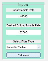
Drop the UpFIRDnConvertor into your design and open the inspector. This shows your input settings and the resulting filter parameters and performance.
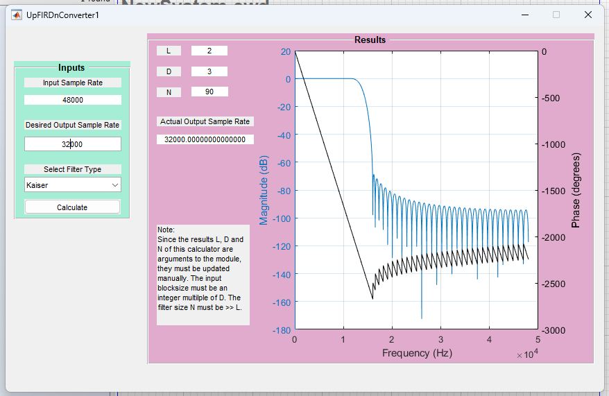
Set the input and desired output sampling frequencies, the filter type, then click on calculate.
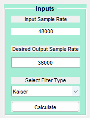
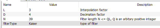
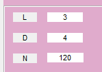
The filter parameters L, D, and N will be shown.
Choose different filter types to see the effect on the stopband attenuation and filter size.
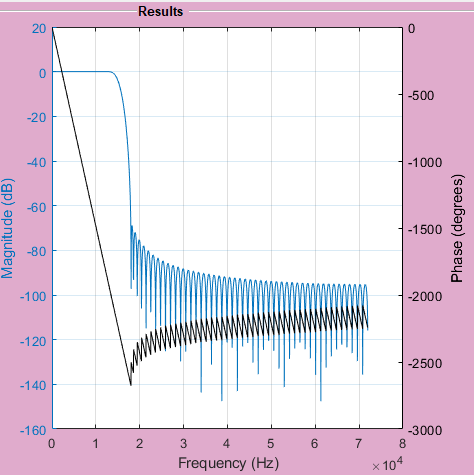
Kaiser filter
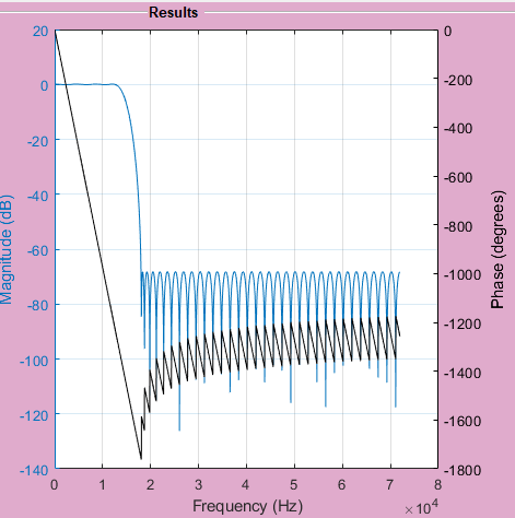
Parks-McClellan filter
In this example, if we had an input block size of 32, we could not implement a target sample rate of 32000 Hz properly as D needs to be a factor of the input block size.
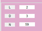
However, with an input block size of 48 bytes, 32000 Hz would be supported as 48 = 16 * 3.
Use the calculated values for L, D, and N to manually set the following Arguments for this Module: