
Wires in Audio Weaver
About This Guide
This Application Note explains the use of Wires in the Audio Weaver Application.
Wires in Audio Weaver
Connections between audio modules are called wires and correspond to buffers of data on the target. This is an analogy to an electronic circuit, where connections between various components are indeed made by metal wires carrying currents. In the case of Audio Weaver layouts, wires between modules create logical connections that are managed by creating connections in software when the layout is instantiated.
A wire has the following properties:
number of channels
block size
sample rate
complexity (real or complex values).
Different types of wires
Audio
Audio wires carry audio signals that you will listen to. Audio wires are represented in the layout by a solid line. The wider the line, the more channels are being carried on that wire.
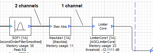
Figure 1. Number of channels sets the wire width
Feedback
Feedback wires are a special case of audio wires, where the destination of the signal is closer to the input pin than the source of the signal. These are displayed in a blue color as shown below.
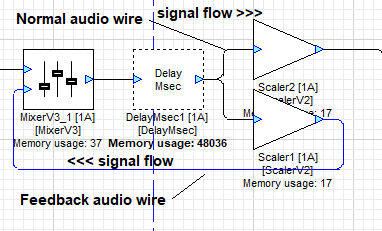
Figure 2. Feedback paths require special handling
Feedback wires will be discussed in detail in the section Feedback.
Control
Control wires carry control signals, which can be non-audio signals used to control parameters of the various modules. For example, a knob which connects to an equalizer stage to control the amount of boost or cut is a control signal. These are displayed as dotted lines as shown.
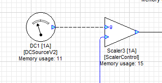
Figure 3. Control wire
Control wires will be discussed in detail in the section Control Signals.
Data types
Audio samples are represented as 32-bit values. Three different data types are available:
Float – standard 32-bit floating-point with 1 sign bit, 8 exponent bits, and 23 mantissa bits.
Int32 – Standard two's complement 32-bit integer. The signed values are in the range [-231, +231).
Fract32 – Fractional representation where values are scaled in the range [-1, +1). This is a fixed point representation with an implied scale factor of 2-31. The input and output pins of a layout are almost always in fract32 format.
Block sizes and number of channels
The number of channels and block size of a wire is called its size. Show wire properties using the View→Wire Info menu item. When enabled, you will see the details of each wire displayed as shown below. The sample rate and data type are also shown.
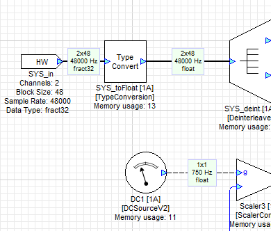
Figure 4. View->Wire Info
Most modules can operate on an arbitrary number of channels and block size. When a chain of modules is connected using a multi-channel wire, the processed result is the same as if you had deinterleaved the data to individual channels and sent each one through a single-channel chain of modules.
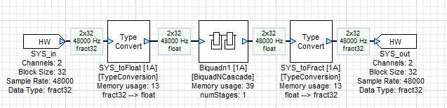
Figure 5. Multichannel modules
is functionally equivalent to
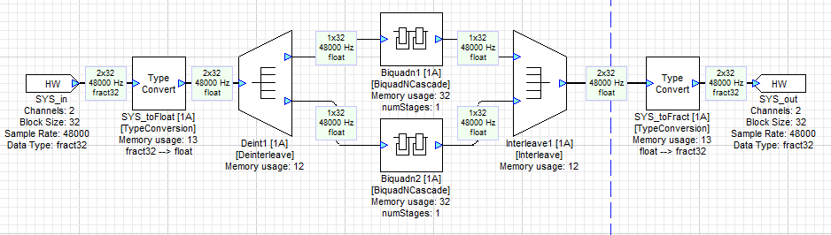
Figure 6. Single channel module equivalent
However, since wire connections also consume memory, the first layout which uses fewer modules (and therefore connections) uses less memory.
How complex data is supported
Complex data includes real and imaginary parts. Voltages in electronic circuits are always real. Complex audio data arises when the real audio data is transformed from the time domain (signal waveform) to the frequency domain (spectrum). The imaginary part, in conjunction with the real part, allows you to measure both the magnitude and phase relationship of individual frequency components. Audio Weaver natively supports complex data within wire buffers. The data is stored in an interleaved fashion:
real[0], imag[0], real[1], imag[1], real[2], etc.
For multichannel data the interleaving of real and complex data happens at the lowest level. For example, interleaved stereo data is stored as:
L_real[0], L_imag[0], R_real[0], R_imag[0], L_real[1], L_imag[1], R_real[1], R_imag[1], etc.
If View->Wire Info is enabled, it will mark complex wires with a “C”.
How to convert between data types
Several modules are supplied to convert wires between different data types.
 | RealImagToComplex | Converts two real signals into complex data using one as the real part and the other as the imaginary part |
 | ComplexToRealImag | Converts a complex signal into separate real and imaginary components |
 | Type Convert | Converts between any combination of: float fract32 int The input data type is inherited from the previous module’s connecting wire. The output data type is set in the module’s Properties tab. |
SetWireProperties module
The SetWireProperties module is used to override wire information in an Audio Weaver layout. It is used rarely when you need to change the channel or sample count, or the real/complex properties of a wire.
Here are some typical use cases:
To convert a wire with 1 channel and a blockSize of N to a wire with N channels and a blockSize of 1.
If the BSP code is sending floating-point data to the input pin. The input is always marked as "fract32" in AudioWeaver and the SetWireProperties module can override this to "float".
Assume the sample rate of the input pin is 48 kHz. One of the channels is 3 microphone signals at 16 kHz. Use a Router to pull the data out. Then the SetWireProperties module to turn it into 3 channels with blockSize/3.
Sometimes the sample rate needs to be corrected. For example, you might have a Rebuffer module followed by a BlockStatistics module. The output sample rate will not be correct.
Channel names
You can edit the channel names in a multi-channel wire by right clicking on the wire and selecting “Edit Channel Names” from the popup menu.
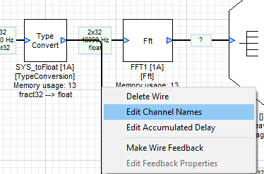
Figure 7. Edit Channel Names Menu Item
This will display a table where you can enter the channel names you wish to use. Be sure also to select the corresponding checkbox to enable channel renaming.
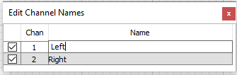
Figure 8. Editing the channel names
Select View->Channel Names to display the channel names along with the wire information.
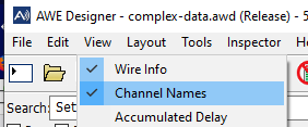
Figure 9. View Channel Names Menu Item
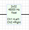
Figure 10. Wire Info Displayed in Layout
Accumulated Delay
If your layout includes modules which delay the signal, the “View->Accumulated Delay” menu option will display the total delay (in samples) up to that point from the input pin.
The example below shows a layout with two DelayMsec blocks in series. The Accumulated Delay of the second DelayMsec block shows the delay, which is the sum of the incoming delay (12000 samples) and its own internal delay (5760 samples) for a total of 17760 samples.
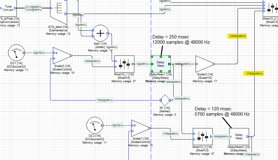
Figure 11. Showing Accumulated Delay
You can edit the accumulated delay on any given wire by right-clicking on the wire and selecting the “Edit Accumulated Delay” option from the popup menu.
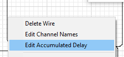
Figure 12. Edit Accumulated Delay
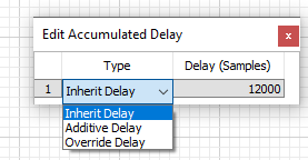
Figure 13. Accumulated Delay Options
There are three options:
Inherit Delay - this uses the accumulated delay from the wire’s source pin and passes through to the next module unchanged. The delay value is not editable when this option is selected.
Additive delay - the value you enter into the Delay field will be added to the inherited delay from the previous module. The entered value should be greater than or equal to zero.
Override Delay - The delay value will be set to whatever you enter into the Delay field. The value should be greater than or equal to the inherited delay.
Control Signals
Control signals are distinct from audio signals in that they are used to allow adjustment of a parameter in a given module by using a signal from a controller module. Generally, you do not listen to control signals.
Control signals:
Are generated using source modules (DC Source, sine wave, noise, etc.)
Set the block size of the source to 1 sample
Are generated as intermediate results from certain modules (BlockStatistics, RMS, etc.)
These modules do not have a block size setting
Are shown as dashed lines in AWE Designer
All modules can operate on control signals.
There are some special modules with control inputs built-in
SecondOrderFilterControl
ScalerControl
ParamSet turns any module into a controllable module. The ParamSet module takes a signal from an input wire and writes the value to an instance variable in another module. The module is useful for controlling the behavior of other modules in response to control signals or audio signals. See ParamSet for details.
Using the Copier module
If you are editing a subsystem and need a signal to pass directly from an input to an output, you’ll need to use a Copier module in the middle. You should not need to use the Copier module in any other situation. See the Subsystems Application Note for more information.
Feedback
Feedback wires
When you create a signal path where the source of the signal is “downstream” of the signal’s destination, this is known as a feedback loop. An example is given below.
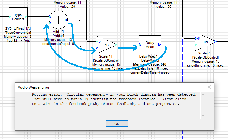
Figure 14. Circular path routing error
Note that a wire going from right to left in the layout does not always cause a feedback loop. Only if a signal’s path as traced through any given set of modules can come back to the source of that signal is a feedback loop created.
If you attempt to run this layout, an Audio Weaver error dialog will be shown. You’ll have to figure out where the loop is and then set the wire properties to make it a Feedback wire.
To mark a wire as Feedback, do the following:
Highlight the wire with the mouse (right-click)
Choose “Make Wire Feedback” from the popup menu. The wire turns blue.
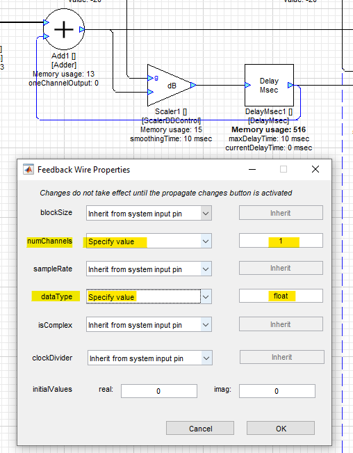
Figure 15. Updating the Feedback wire's properties
Now you will have to set the wire properties, which will otherwise be inherited from the input pin. At the minimum, you will typically need to set:
numChannels
dataType
Make sure that these values match the properties of the source block’s output pin. Turn on Wire Info view if needed (View->Wire Info).
If you have Markers in the feedback path, you only need to mark the last segment as “Feedback”. Wire “Z” below is correctly assigned as “Feedback”.
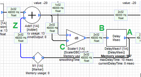
Figure 16. Feedback path identified
Block latency
A feedback path introduces a single sample of latency to that path. The reason for this is that the value of the signal on a feedback path is saved during one sample period and used during the next sample period. Refer to Figure 16 above. Since output A of the DelayMsec module which drives the feedback wire Z depends on its input B which depends on C which depends on Z, this signal cannot be calculated in a single cycle. Marking a wire as “Feedback” adds a single sample buffer. The signal on the highlighted Feedback wire was calculated on the previous cycle compared to everything else.
Debugging failures
Check the layout by clicking on “Propagate Changes” or “Build and Run”. If there is an error, you will hear a system sound and the associated wires will be shown with “?” in the Wire Info. In the example below, the error is that the adder is expecting two channels on all inputs, but we set the blue feedback wire’s numChannel property to 1. Notice that the errors start just downstream of the wire that is causing the problem.
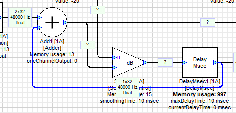
Figure 17. Wire properties unknown
Changing the blue feedback wire’s numChannels property to 2 removes the error after you click on “Propagate Changes” or “Build and Run” again.
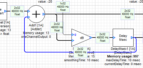
Figure 18. Wire properties updated
Why you must specify the wire properties
In general, a module determines its input pin properties by reading the pin properties of the incoming wire. When the design layout is instantiated, the various code branches are traversed from input to output. When you encounter a feedback wire, its value and properties have not yet been parsed. To allow the code generator to proceed, you must manually override the properties (or inherit the property from the input pin).
Interactions with Module Status
The feedback wire along with the Copier module can be used to control the status of the feedback loop. In the example shown below; the output of the adder is fed back into the second input of the adder via a feedback loop. To control the status of the feedback loop we have added a Copier module before the feedback wire. The status of the feedback wire is being controlled byStatus Set Module which in turn gets the input from Feedback_DC.
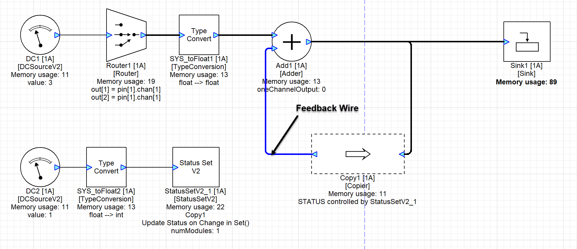
Figure 19. Controlling feedback wire status
In this example by changing the Feedback_DC value to 3 then the Copier module becomes inactive effectively stopping the feedback loop and stopping the output of the adder. Whereas when the Feedback_DC value is 2 the Copier module becomes mute and starts pumping zeros instead into the feedback loop. The output of the Adder is the value of Adder_Input1 in this case.
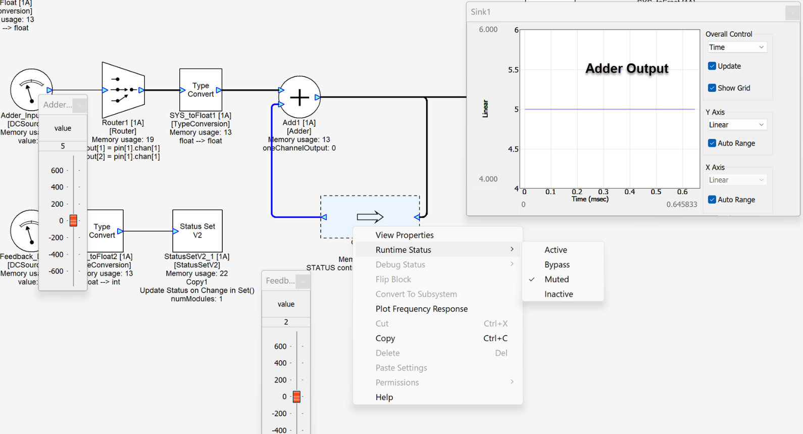
Figure 20. Controlling feedback wire status