
Logic
This section contains the following pages:
Control Signals and Boolean Logic
Control signals are defined as having a block size of one. This useful for reducing the computational load when only a single value is needed. Wires holding control signals are shown as dashed lines (--------->).
To illustrate the use of control signals we’ll build up a Fletcher-Munson equal-loudness contour. This guide is not intended to go into depth on topics of audio processing, but in simplest terms, this system adapts frequency as the level of audio drops. The human ear perceives both the low- and high-range frequencies dropping off more quickly than the mid-range frequencies. A common method for dealing with this in audio processing is to boost the bass and treble frequencies as the volume drops to create what is called an “equal-loudness contour,” or a “Fletcher-Munson curve.” This can be achieved by a filter which varies based on the desired volume level. This example will demonstrate the process, including the use of several control signals.
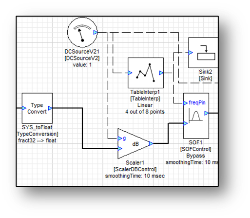
The complete system (shown below) has a few key points. As the volume is reduced at the DCSource, the levels of the bass and treble frequencies will be boosted so that they sound as though they are dropping off at the same rate as the mid-range frequencies. Note the dotted lines representing all the control signals. This implementation is also computationally efficient. The control signals have a block size of 1 and do not require much computation. The main processing is performed by the Scaler and two SOFControl modules.
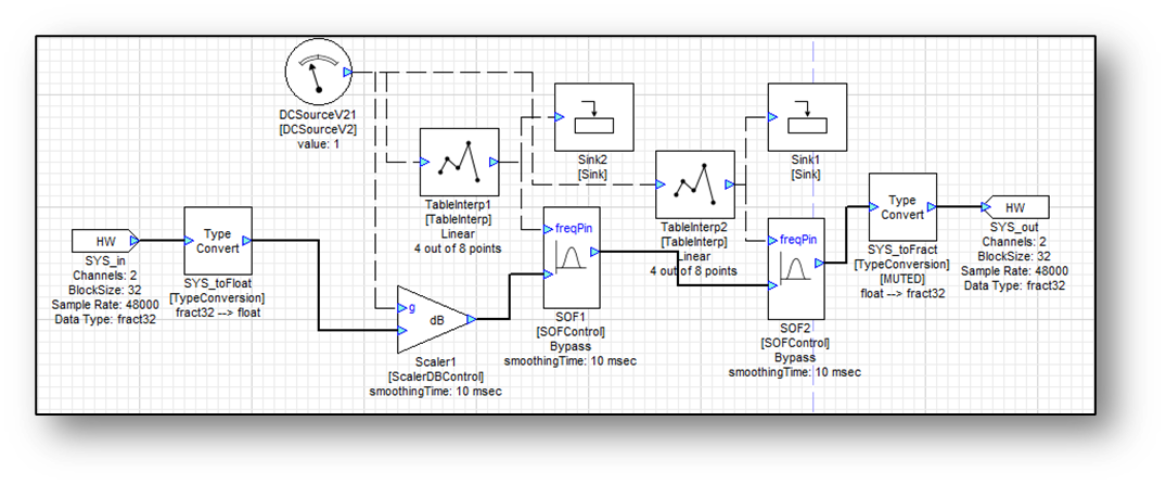
The VolumeSetting module is a DCSource which outputs the gain setting, in dB; this is a control signal and is drawn as a dotted line. When configuring the VolumeSetting using module properties set its blockSize and number of channels to 1.
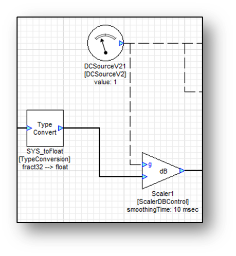
The first step is to reduce the signal level by VolumeSetting. This is accomplished using the ScalerDBControl module. This module takes its gain setting from an input pin rather than from an inspector and allows for a control signal-dependent gain.
 | ScalarDBControl | Simple dB scalar; gain controlled by control signal input |
In this example it will be used to allow a DC source to adjust the overall volume. Thus begins the system as shown below:
Another example of a control signal module is the SOFControl module.
 | SOF Control | Second-order filter with gain determined by control signal input |
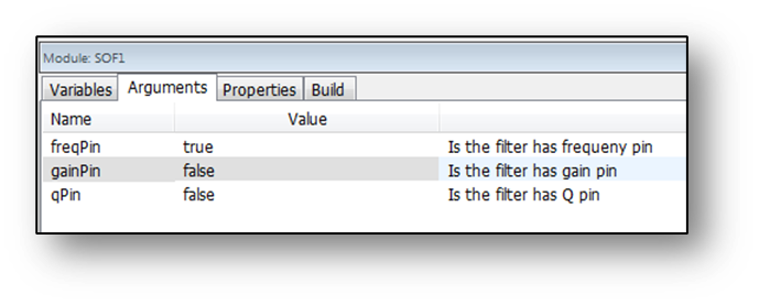
The SOFControl module allows for a control signal to adjust parameters (frequency, gain, or Q) of a second order filter. The control parameter(s) are selected in the module’s module properties. In this case, only the gain is controlled as shown below:
In this example, this will allow for a volume-dependent bass (and treble) boost. The SOFControl module will take in the audio from the Scalar module as one of its inputs (the lower input pin):
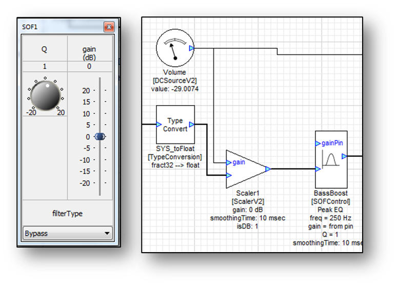
Since the purpose of this filter is to boost bass frequencies, a filter type of “Peak EQ” and a frequency of 30 Hz are selected in the module’s inspector. The upper input pin of the SOFControl module requires a control signal input. This control input will originate from the DCSource controlling the volume. To achieve the equal-loudness contour, the bass must be boosted in relation to the volume. The mapping between the volume and the bass boost is accomplished with the TableInterp module:
 | TableInterp | Second-order filter with gain determined by control signal input |
The TableInterp module allows the user to map out the intended input-output relation visually and interpolates between given points to produce a continuous function. In this case, the relation shown below will be sufficient:
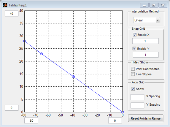
At full volume (0 dB) there is no bass boost. As the signal level drops more boost is progressively applied. At -80 dB 28 dB of boost is applied. Also note that the table interpolation both takes in and outputs a control signal. Only a single value is translated through the table’s function at a time.
A sink module can be appended to the output of the table interpolation to show in real-time the computed gain. Note that when the sink module is given a control signal as input, it will only display the single value, rather than the graph it normally displays.
This has accomplished the boosting of the bass frequencies, and the same strategy can be employed to boost the treble frequencies. This SOFControl will be set to alter the treble frequencies, with a filter type of “Shelf High” and a frequency of 6000 Hz:
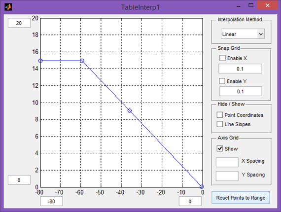
This TableInterp will use a slightly different relation but will achieve fundamentally the same function – boosting the level at lower volumes:
Boolean Signals
A Boolean signal has only two possible values, 0 and 1. Boolean data is useful for controlling systems. Boolean signals are represented using 32-bit integer values. Audio Weaver includes several modules that perform logical operations on Boolean signals.
 | BooleanInvert | Inverts a Boolean signal (logical NOT gate) |
 | LogicAll | Resolves to 1 if and only if all its inputs are non-zero (logical AND gate) |
 | LogicAny | Resolves to 1 if any of its inputs are non-zero (logical OR gate) |
By default the LogicAll and LogicAny modules do not have any output wires; they store the output in an internal variable (“.result”). By checking the box next to “outputValue” in the module properties, an output pin can be created.
 | LogicBinaryOp | Performs binary operations on Boolean data |
The LogicBinaryOp module allows the user to select a logical operation (logical AND, OR, and XOR). It takes two control signals as input and outputs one wire with the computed Boolean value.
 | BooleanSource | Source module with Boolean data output |
The BooleanSource module is a source module that supplies a buffer of Boolean data. As with any source module, the number of channels, block size, and sample rate are user-specified in the module properties.
 | LogicCompare | Compares input values |
 | LogicConstCompare | Compares input to constant |
The LogicCompare module performs one of many possible comparisons on two input values. In its Inspector is a drop-down menu of the possible comparisons: EQUAL, NOTEQUAL, LESSTHAN, LESSOREQUAL, GREATERTHAN, and GREATEROREQUAL.
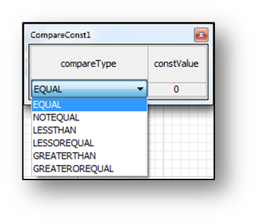
The module performs the comparison and outputs 1 if the comparison resolves to true and 0 if it resolves to false.
The LogicConstCompare module functions the same way, except it compares a single input to a constant, user-specified value.
A simple example of the use of the Boolean signals is shown below. This system selects the louder of the two input channels and outputs it on both channels. To accomplish this, the RMS module measures the levels of the two input signals and outputs control signals. These control signals are then fed into a LogicCompare control, set to LESSTHAN comparison type. Its output controls the index of the MultiplexorFadeControl module which selects the louder of the two input channels.
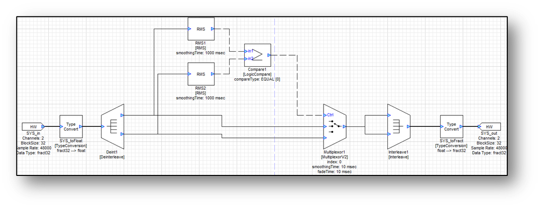
If RMS1 < RMS2 then the LogicCompare module outputs 1 and the louder right channel is selcted; if RMS1 >= RMS2 then the module outputs 0 and the louder left channel is selected.
ParamSet and ParamGet
Control signals can be used to adjust parameters of modules. This can also be accomplished with the Param Get and Param Set modules. These are found in the Misc. folder. The example from the previous section can be made even cleaner by using ParamSet.
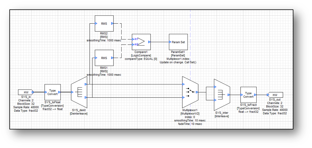
The output of the LogicCompare module is fed straight into the ParamSet module, which in turn sets the index of the MultiplexorFade module. Note that in this version, the multiplexor does not have to be a control module.
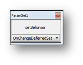
Just like ParamGet, the target parameter is specified in the module properties, with “name of the module”.“parameter to be set”. Also specify the data type of the input wire. In its Inspector, the ParamSet module allows the user to change the when the parameter update occurs using the setBehavior drop-down menu:
The choices available are:
AlwaysNoSet — Always update the variable in the instance structure. Do not call the module’s set function.
AlwaysDeferredSet — Always update the variable in the instance structure. Call the module’s set function in the deferred processing thread.
OnChangeNoSet — Only update the variable when it has changed. Do not call the module’s set function.
OnChangeDeferredSet — Only update the variable when it was changed. Call the module’s set function in the deferred processing thread.
OnChangeInstantSet — Only update the variable when it has changed. Then call the module’s set function from the real-time thread. Change occurs immediately.
The many options allow for optimization of computational efficiency by performing the change at a time when it is most appropriate for the system. In most cases, the OnChangeDeferredSet is the most appropriate.