
Signal Management
This section contains the following pages:
General Information
Signal management modules are modules that manipulate the flow of data. This is done on a few different levels. The marker module is a simple fix to wiring components overlapping, and has no effect on the runtime algorithm. This module can also be used as test points to view signal response. There are also modules that control channel flow, allowing interleave/deinterleave, or even the routing of one channel into another, and finally the multiplexing to choose between various signals. Data type conversion occurs when the samples are all converted into another numerical format. The more complicated modules in this folder control block flow and sample flow.
Multiplexors
Multiplexors (or Muxes) are logic elements that allow different signals to be selected based on an index (or control) value. Muxes are useful for setting up A/B comparisons to allow accurate comparison of two different signals. Multiplexors support multichannel signals and the number of input pins (number of signals to select from) is specified as a constructor argument.
There are 3 different types of muxes:
 |
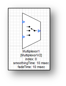
Multiplexor (MultiplexorV2 & MultiplexorV2Fract32)
| Supports smoothing for switches and crossfading into/from silence. Index taken from inspector or from an optional control pin. Float and Fract32 versions. |
 | Multiplexor Unsmoothed (Multiplexor) | Just copies data; no smoothing Supports any 32-bit data type |
 | Sample Multiplexor Control | Sample based mux, no smoothing Only has control pin |
If the signals that are switched between is a control signal or a signal where discontinuity is not important, then choosing 0 smoothing or 0 fade time has computational advantages.
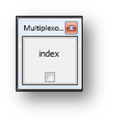
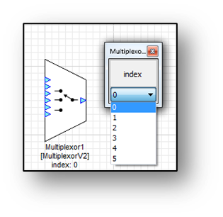
The index variable is zero based and determines which signal is selected. If there are two signals to select from, then the inspector is drawn as a checkbox. Unchecked (zero) selects the first signal and checked (one) selects the second signal.
If there are more than two signals to select from the inspector has a drop list:
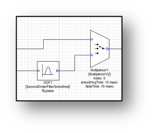
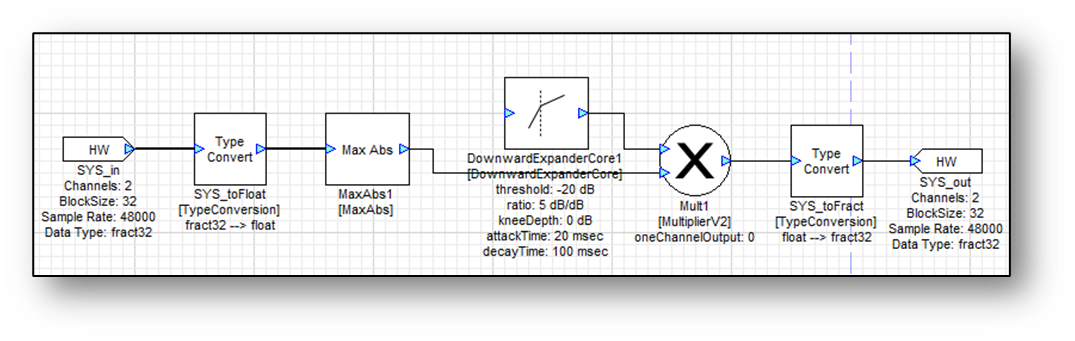
Here are a few examples of how to use a multiplexor module in practice. MultiplexorFade performs seamless crossfading between signals. In this first example, the multiplexor is being used to enable an optional equalizer.
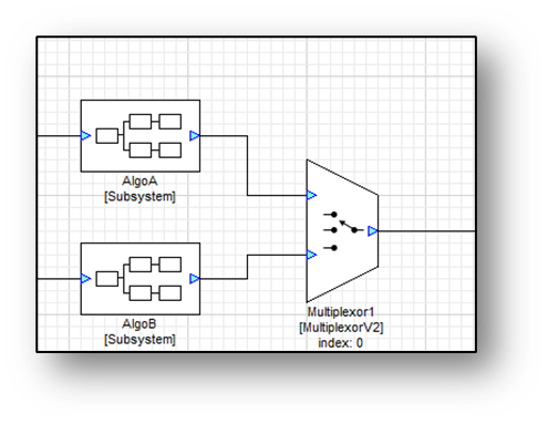
In the next example, 2 different versions of an algorithm are compared to see which one sounds better. This is a classical “A/B” comparison in audio.
Marker
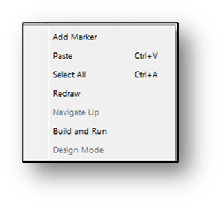
The Marker module is used label wires in the design and also to make wire routing prettier. The Marker module is a virtual mode and is removed from the system when it is built. The Marker module is very frequently used. Add a Marker module to the layout by right-clicking on an empty portion of the canvas and selecting Add Marker.
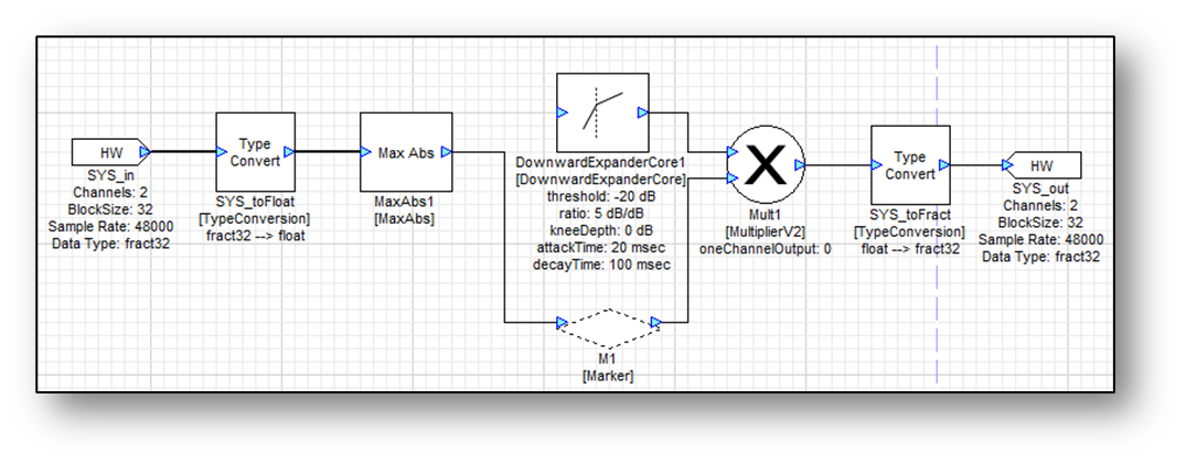
Below is an example of how to use the marker module to clean up a design. Initially the wire goes through the text label of a module making it difficult to read.
Now reroute the wires with as few or as many markers as needed.
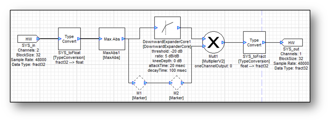
The second use of the Marker module is in computing frequency responses. get the frequency response of an individual filter by right-clicking on it and selecting “Plot Frequency Response”. With a chain of filters, insert Marker modules at the input and output wires.
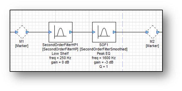
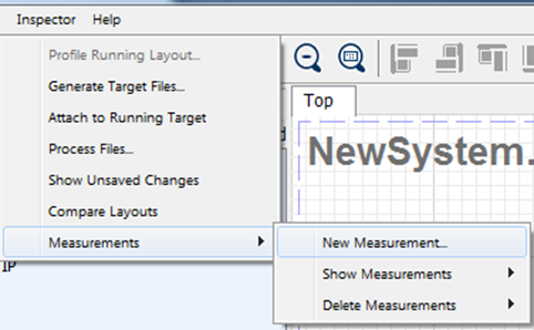
Then using the Measurement menu plot the frequency response between Markers M1 and M2. This is given in Tools->Measurements.
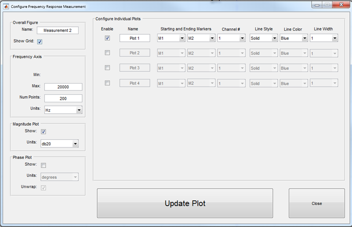
The measurements made will be saved here, allowing for easy updating of plots.
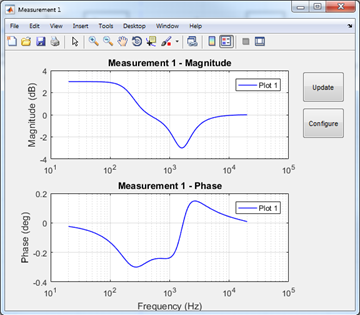
Finally, the plot will pop up in its own window with the standard MATLAB plot capabilities, as well as an “update” button to redraw the frequency or phase response of the system. Use this to see how filters are responding with each other. This is based on the filter coefficients, so this feature doesn’t work on every module. For reading the output of modules, use the sink modules.
Interleave/Deinterleave
Two of the most basic modules are the Interleave and Deinterleave modules.
 | Deinterleave
| Turns multichannel signals into separate mono signals. |
 | Interleave
| Combines multiple mono channels into a single interleaved signal. |
These modules are part of the default system which is created when starting a new design. For the Deinterleave module specify the number of output channels on module properties and it must match the number of input channels. If there is a mismatch an error will pop up when the system is built.
The Interleave module takes N input signals and combines them into a single multi-channel output. The number of input pins is specified by module properties. One special property of the Interleave module is that not all input pins have to be mono. In fact, any number of channels per input pin converts to the output simply “stacking” all of the input channels.
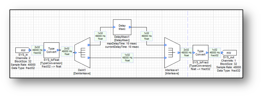
In the first example, a stereo input’s left channel is delayed by 10 msec.
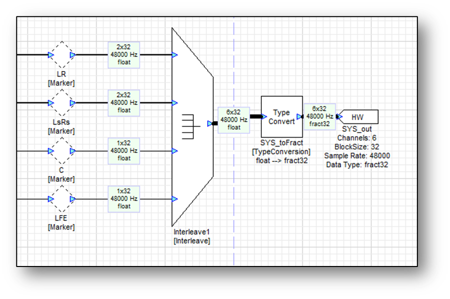
In the next example two stereo signals (L/R and Ls/Rs) are combined together with two mono channels (C and LFE) to form a 6 channel output. The channels in the interleaved output pin will be ordered: L / R / Ls / Rs / C / LFE.
Router
The Router module simply copies input channels to output channels. The module solves many common signal management issues like selecting or recombining channels and in most cases is more efficient than using Interleave and Deinterleave modules.
 | Router
| Copies and combines audio channels. No smoothing. |
 | RouterSmoothed
| Copies and combines audio channels. With smoothing. |
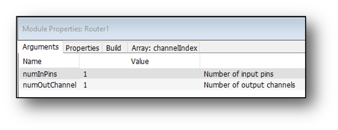
In its most general form, the Router module has M input pins and N output channels. The numbers M and N are specified on the module properties:
For simplicity, we’ll start with a single input pin and then build up to the more complicated case of multiple input pins.
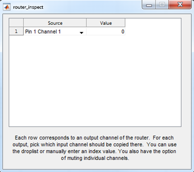
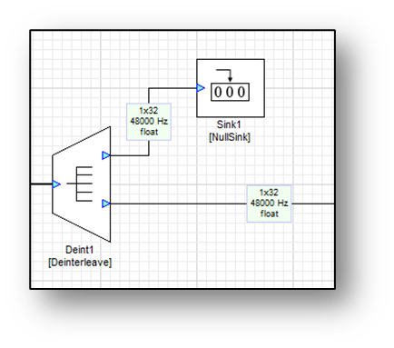
In order to use the Router module effectively, how the channel routing map is specified must be understood. The module has a .channelIndex array of length N, where N is the number of output channels. The input channel to copy to the nth output channel is specified by channelIndex[n] and the channels are ordered starting with 0. Let’s start with a simple example. Suppose that a stereo signal needs the right channel extracted. This can be accomplished with two modules as shown below. The NullSink module is used to tie off the unused left channel output.
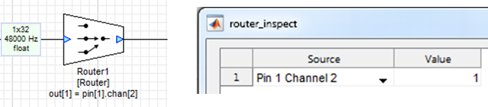
Alternatively, the same function can be accomplished with a single router module. Configure it for a single input pin (M=1) and a single output channel (N=1). Then set channelIndex[0] = 1. This copies the right channel (the second channel is chosen due to the index set to 1) to the first output channel.
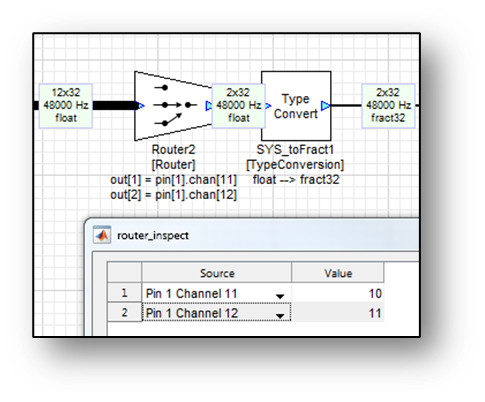
In the second example, a sound card with 12 input channels is used. The 2 target audio channels are contained in the last two input channels. In this case, configure the router module for 1 input pin and 2 output channels. Then set the channelIndex array as shown to the right.
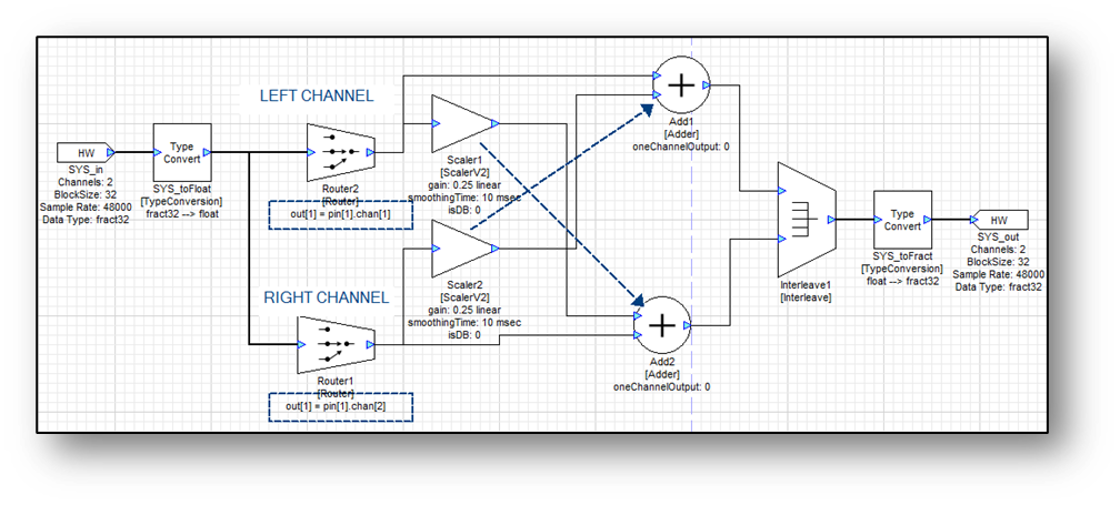
For the final example, crossfeed between the left and right channels. That is…
𝐿𝑜??𝑡=𝐿𝑖𝑛+0.25𝑅𝑖𝑛
𝑅𝑜𝑢𝑡=𝑅𝑖𝑛+0.25𝐿𝑖𝑛
The router module can be used to swap the order of the left and right channels making it easy to implement the crossfeed utilizing stereo processing.
Consider the case of a router module with multiple input pins. Each element of the channelIndex[] array is treated as a 32-bit unsigned integer and packs in a pin# and channel# as follows:
channelIndex[n] = (pinNum << 16) + channelNum
That is, the pin number is in the high 16-bits and the channel number is in the low 16 bits. Thus far, all examples have had a single input pin starting at pinNum = 0 setting the focus on channelNum, some positive integer offset.
Suppose that there are two wires holding 5.1 channel data. The channels are ordered as L0 / R0 / Ls0 / Rs0 / C0 / LFE0 in the first wire and L1 / R1 / Ls1 / Rs1 / C1 / LFE1 in the second wire. The goal is to form a new 5.1 channel signal by combining the signals as L0 / R0 / Ls1 / Rs1 / C0 / LFE0. This can be accomplished with a single router module as follows.
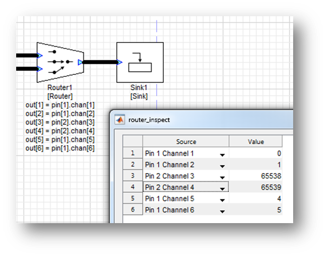
The values in the channelIndex array are computed as:
Pin 0, Channel 0 à (0 << 16) + 0 = 0
Pin 0, Channel 1 à (0 << 16) + 1 = 1
Pin 1, Channel 2 à (1 << 16) + 2 = 65538
Pin 1, Channel 3 à (1 << 16) + 3 = 65539
Pin 0, Channel 4 à (0 << 16) + 4 = 4
Pin 0, Channel 5 à (0 << 16) + 5 = 5
Note: The notation (pin << 16) represents a left shift by 16 bits. Alternatively this equals (pin * 65536).
The Router module can handle any 32-bit data type. The channelIndex array can be changed at run-time and the change in router occurs instantly without smoothing. For a smoothly varying channel router without pops or clicks, use the RouterSmoothed module.