Welcome To AWE Synthesis Tutorial

About This Guide
The Welcome to AWE guide contains instructions for basic usage of modules in Designer to create synthesized sounds from scratch. The example will contain instructions for creating oscillators, modulating pitch with a second oscillator, adding an envelope, pitch randomizer, filter LFO, Delay, and effects like Reverb or Amp simulator.
The finished design and files used for this tutorial are attached below:
WelcomeToAWE_SynthTutorial.awd
FenderAmpCoeffs_backup.csv SmallHallCoeffs_backup.csv
If you are having difficulty downloading the materials or have other questions, please email se@dspconcepts.com
Overview of the design
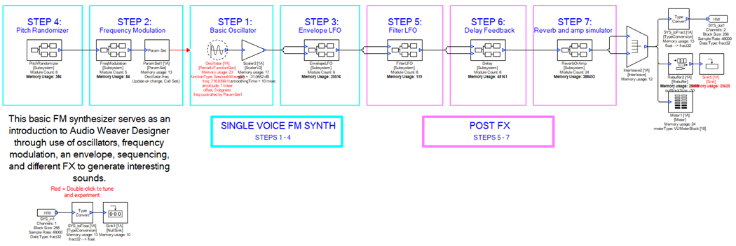
Within the “WelcomeToAWE_SynthTutorial.awd” there are 7 sections or steps to creating the signal flow. In a blank design, there will always be an input and output audio pin labeled “SYS_in” and “SYS_out”. Since all audio is generated from within the design, there is no need for the input pin to bring in audio. We stop the input pin from sending audio by connecting the Type Convert following it, to a Sink module. New modules can be searched for and dragged onto the canvas from the module browser on the left side of the Designer window. Any module with blue in or out pins needs to be connected with a wire for the design to run. The Sink module allows this connection while discarding the input data. We also set block size of the design by right clicking the input pin module, selecting “View Properties”, clicking the build tab in the properties window, and changing the block size from 32 to 256.
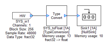
Figure 1. Routing the input pin to a Sink.
Creating optional output tools
Another optional step in preparation, is to add a meter, and scope to the output stage of the design.
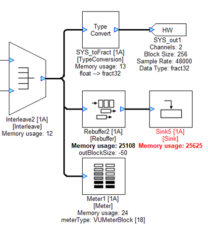
Figure 2. Creating an output Meter and Sink.
Meter
The meter can be added simply by selecting it from the module browser and dragging it onto the canvas, then connecting it to the interleave module which copies the input to a second channel for dual-mono playback.
Rebuffer and sink
In order to view our output signal on a graph like a scope, we first need to rebuffer the input block size to a larger block size so we’re able to view a larger window of the signal. We multiply the input block size by changing the outBlockSize parameter in the Rebuffer module to “-50” as a start, but this can be changed to view different window sizes. Then we connect a sink module to the output, and double click the module to view the signal in real time.
Step 1: Basic Oscillator
This is the beginning of the signal flow. A periodic function generator module is used to output a continuous carrier signal of constant amplitude. A General Purpose Scaler is used to adjust the gain. At the end of this step if you run the design, you should hear a single pitch of a waveform you designate.
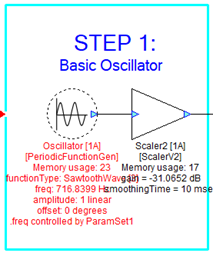
Figure 3. Basic Oscillator
Periodic Function Generator
We use a PeriodicFunctionGen module as the initial audio source of our design. You may choose to use a Sine, triangle, square, saw or impulse waveform. We will learn how to remotely control the frequency in the next step. Lastly, we add a General Purpose Scaler. You may optionally route this to the output pin and run the design to hear the oscillator.
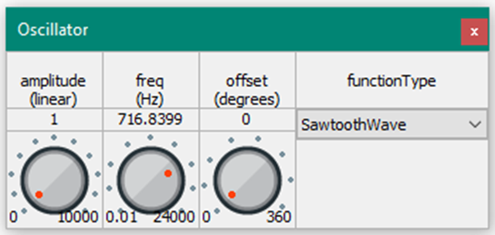
Figure 4. Periodic Function Generator
Step 2: Frequency Modulation
By adding a 2nd, modulating frequency to the main carrier frequency, we create vibrato in the low frequency range, or begin adding harmonics in the audio range. This is the foundation for tons of interesting synthesizer sounds.
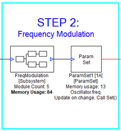
Figure 5. Frequency Modulation
The Frequency Modulation Subsystem
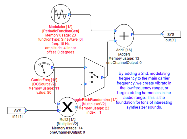
Figure 6. Frequency Modulation Subsystem
Creating a second oscillator
At the top of the above figure, we’ve added a second PeriodicFunctionGen module which will be added to our “carrier frequency” designated by a DC Source module. The carrier frequency should be set to something in the audible range, like 440Hz, as it is our fundamental frequency. The “modulator” (the PeriodicFunctionGen module above) should be set to a low frequency to start, such as 10Hz, and the amplitude set to a whole number, like 4. When the output of these two modules are added together, the output frequency modulates 10 times per second, adding and subtracting the amplitude value to and from the carrier frequency. What we end up with is a frequency control that oscillates between 430Hz and 450Hz, 10 times per second. Next, we will use this value to control the frequency of the initial oscillator we created in step 1.
Note: For now, you can ignore the subsystem input pin, multiplier and multiplexor, as those will be relevant in step 4.
Using param set to control the main oscillator
To remotely control the oscillator from step 1, we use a ParamSet module. We do this by connecting the output from our FM subsystem to the input pin of ParamSet, and setting the modVar parameter in the Arguments tab to “Oscillator.freq” as it’s the name and parameter of the module we want to control.
Step 3: Envelope LFO
Without an envolope, an oscillator would have no way of starting or stopping. When you press a key on a synthesizer, you are essentially opening and closing a gate for that oscillator. In its most basic form, an envelope would look like a square wave, but allow time for the gate to slowly open or close and you've created an "attack" time and "release" time. Other envelope stages include "sustain" and "decay".
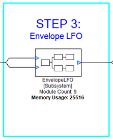
Figure 7. Envelope LFO
The Envelope LFO Subsystem
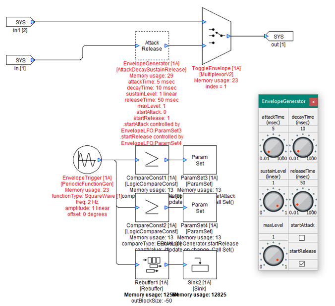
Figure 8. The Envelope LFO subsystem
Adding an Envelope Generator
The initial step taken in the example, is to create two paths for the signal. The first path passes through the subsystem unaffected. The second path makes use of an EnvelopeGenerator module. We use a multiplexor to effectively bypass the envelope as desired. Set the multiplexor to 1 (checked) to enable the envelope.
Using an Oscillator to trigger the envelope stages
In this example we want to control the “attack” and “release” stages of the envelope. Starting with a PeriodicFunctionGen module, we set it to output a square wave at 2 Hz with an amplitude of 1. This will be used to trigger the attack and release stages one time each per second. By using 2 LogicCompareConst modules, we can set one to output “true” if the oscillator equals 1, and the other to output “true” if the output equals 0. Next we route 2 ParamSet modules to the EnvelopeGenerator.startAttack and EnvelopeGenerator.startRelease parameters. We’ve initially set the attack times and release times to 5ms and 50ms respectively, but adjusting these values can yield interesting results!
Step 4: Pitch Randomizer
Here we create a periodically randomized whole-number multiple of the fundamental frequency of our synth. Whole number multiples of a frequency replicate the harmonic series, a naturally occurring sequence of pitches from which all music is formed.
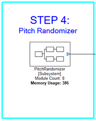
Figure 9. Pitch Randomizer
Random Generator
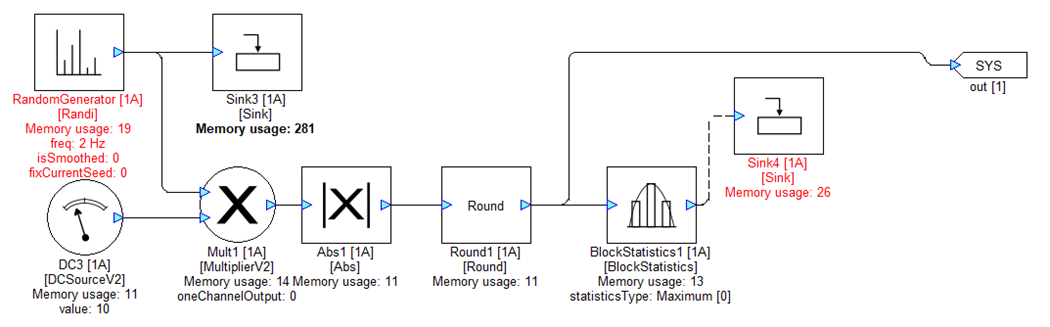
Figure 10. Pitch Randomizer Subsystem
We use a Random Generator module to output a decimal value between -1 and 1 at a frequency we determine. Since previously we set the envelope to trigger twice per second, we’ll also set the frequency of the Random Generator module to 2Hz. Then we multiply the decimal value by 10 to get a decimal value between -9.999 and 9.999. Since we ultimately want to multiply the fundamental frequency of our oscillator by a positive whole number, we take the absolute value, then round to the nearest whole number. The Block Statistics module and Sink modules seen in the above figure are placed to aid in viewing the current generated value.
Connecting the pitch output to the Oscillator
Lastly, connect the output of the number generator to the frequency modulation (step 2) subsystem with a multiplexor to be able to toggle pitch randomization on or off.
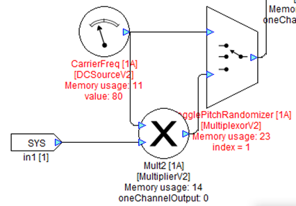
Figure 11. Connection to the Frequency Modulation Subsystem
Step 5: Filter LFO
By using a sine wave oscillator at a low frequency of just a few hertz, we can use the signal to control the cutoff of a low-pass filter. This subsystem was given two inputs to provide a bypass path.
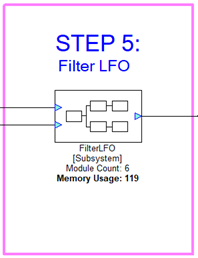
Figure 12. Filter LFO
Controlling a Second Order Filter
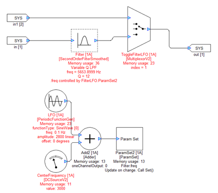
Figure 13. Filter LFO Subsystem
Begin by inserting a Second Order Filter module set to “VariableQLPF” in the signal path. Using the same technique as in Step 2, we remotely oscillate the cutoff frequency of the low pass filter between 200Hz and 5800Hz (3000Hz +/- 2800).
Step 6: Delay Feedback
To create an echo effect, we must add a feedback wire downstream of a delay module. As the signal feeding back is added back into the original “dry” signal, we use a scaler to control how much of that original signal feeds back.
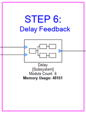
Figure 14. Delay Feedback
Filtering the delayed signal
After creating a simple bypass path, the delayed path is created by adding an Adder module, DelayMsec, then two Second Order Filters set to high shelf and low shelf. These are placed to created a filtered delay effect.
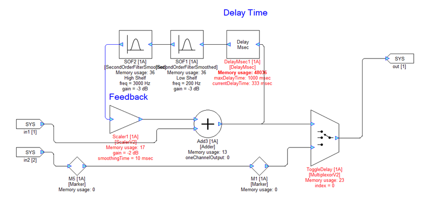
Figure 15. Filtered Delay Subsystem
Creating a feedback wire
An error will occur if a wire feeds back in a system that has not been designated as a feedback wire. To do so, right click the wire feeding back and select “Make Wire Feedback”. Then fill in the corresponding data type of the wire, or other information as appropriate.
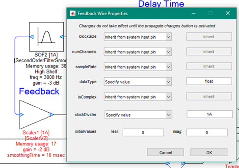
Figure 16. Creating a Feedback Wire
Step 7: Reverb and Amp Simulator
Additional effects are created by loading preset coefficients into a long FIR filter.
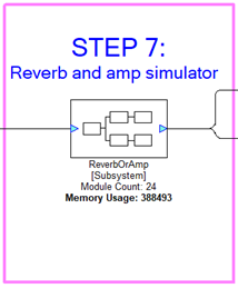
Figure 17. Reverb and Amp Simulator
Creating the effect paths
First we create two paths for the input signal, one will go through a Reverb effect, and the other through an amp simulator. The Reverb path is given an additional path to flow into a Wet Dry module, which allows the user to turn a knob which determines how much of the affected signal is mixed into the unaffected or “dry” signal. Lastly we add a multiplexor to switch between the desired effects.
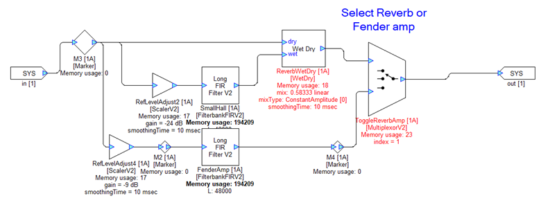
Figure 18. Reverb and Amp Simulator Subsystem
Importing FIR coefficients
For the last step in this application note, we import desired filter coefficients, or in this case presets for a Reverb and Amp Simulator effect. Do so by right clicking the FIR filter modules and importing an array of values.
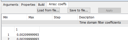
Figure 19. Importing FIR Coefficients
Conclusion
Lastly, run the design and hear the full system generating audio. Red text has been placed throughout the example design to indicate where changing values in the adjacent modules can alter the signal flow. While running the design, experiment with each of the subsystems to create unique and interesting sounds.